
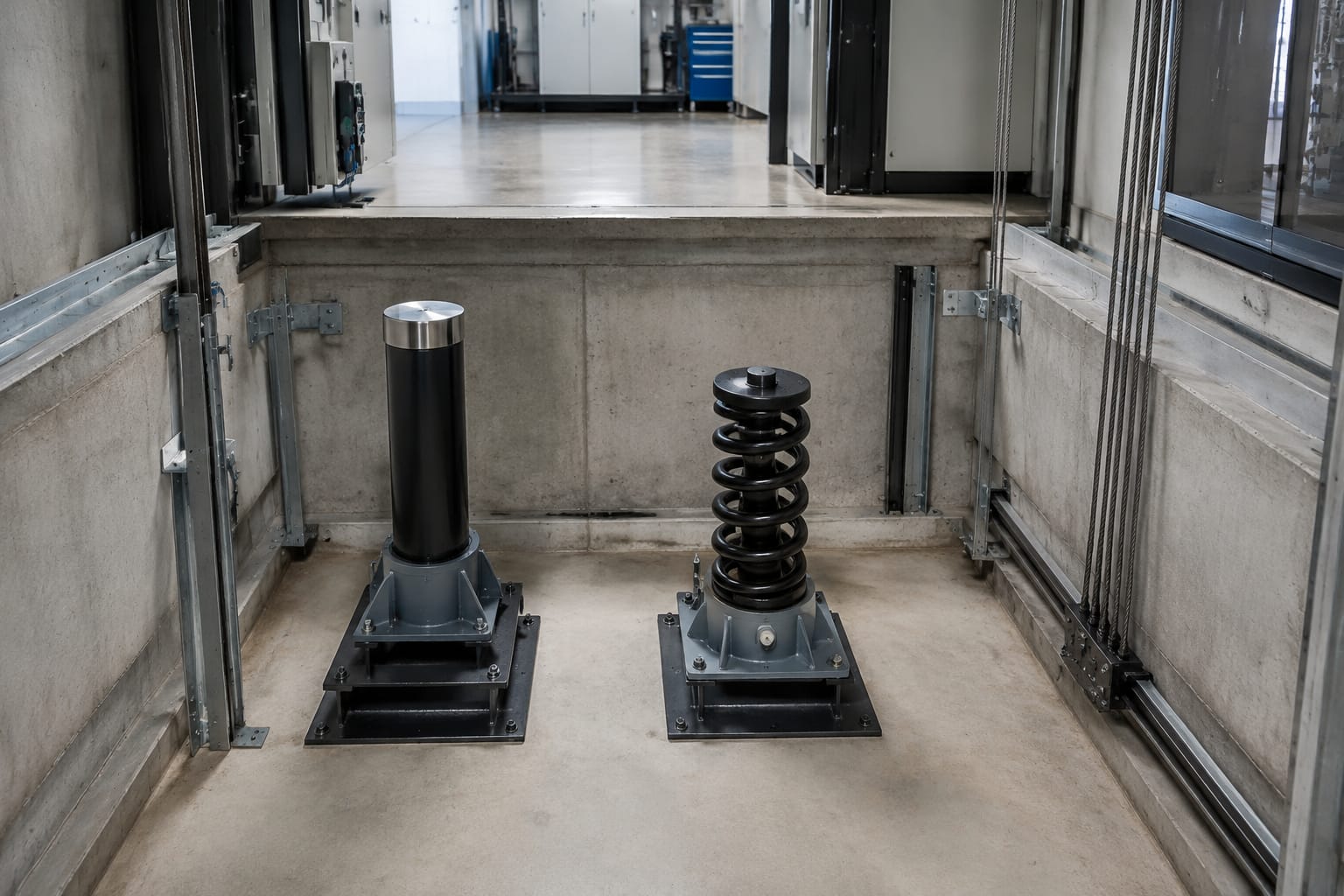
A buffer lift assembly is the final energy-absorbing safety device at the bottom of a lift shaft. It supports the car or counterweight only after it has travelled beyond its normal stopping position, reducing the severity of an overtravel event. Selecting or replacing one is therefore not a matter of matching its outside shape alone: the buffer type, rated speed, permissible mass, stroke, mounting arrangement and electrical proving must all suit the installation.
For most passenger and goods lifts, the practical choice is between a spring buffer for lower-speed duty and an oil buffer for higher-speed duty. The original lift documentation, buffer data plate and governing safety requirements should determine the final selection. A competent lift person should inspect and test the complete safety chain after any buffer work.
What an elevator buffer does
Lift buffers sit in the pit below the car and counterweight travel paths. They form the last mechanical stopping point if either moving mass overruns its normal lower terminal position. A correctly specified buffer absorbs or stores the kinetic energy of the car or counterweight and limits deceleration within the design assumptions of the lift.
A buffer is not a normal stopping system. The lift controller, terminal switches, final-limit devices and safety gear should prevent a car from reaching it during normal service. Repeated buffer contact indicates a fault that needs investigation, not a condition to accept as routine.
The main protective function differs slightly by type:
- A spring buffer compresses and stores energy in its spring arrangement, then returns that energy as the spring expands.
- An oil buffer uses a piston moving through hydraulic oil to dissipate energy over its stroke. It is generally more suitable where controlled deceleration and greater energy absorption are needed.
The pit layout must preserve the specified clearances, supports and travel spaces. A buffer that is physically present but incorrectly positioned, badly corroded, unproven electrically or mismatched to the lift can undermine the safety function of the whole installation.
Oil buffers versus spring buffers
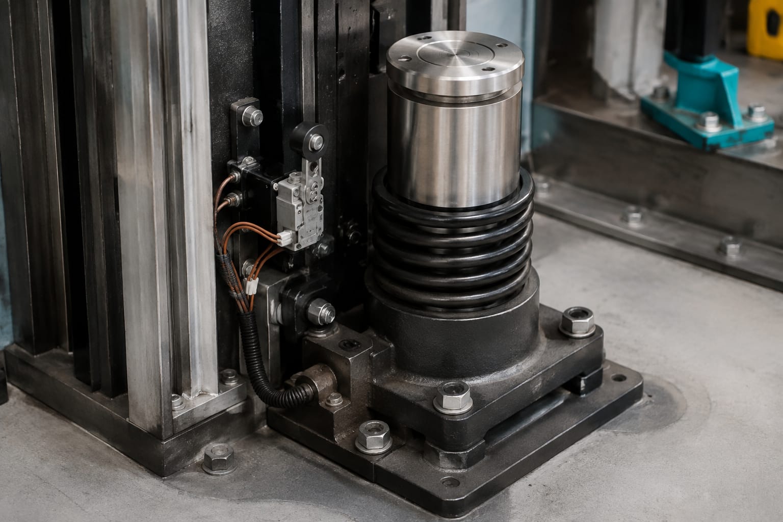
Spring and oil buffers are designed for different operating ranges. They cannot be treated as universally interchangeable alternatives, even when their base dimensions or mounting bolts appear similar.
| Feature | Spring buffer | Oil buffer |
|---|---|---|
| Energy handling | Stores energy through spring compression | Dissipates energy hydraulically |
| Usual application | Lower-speed lifts, subject to the applicable requirements | Higher-speed lifts and installations needing controlled retardation |
| Return after compression | Spring force extends the unit | A return arrangement restores the piston, depending on design |
| Key inspection focus | Broken coils, permanent set, corrosion, seating and alignment | Oil level, leakage, piston condition, corrosion, return condition and stroke |
| Replacement risk | Incorrect spring characteristics or height | Incorrect rated speed, mass, stroke, oil condition or switch arrangement |
| Electrical proving | May be used where specified | Commonly critical where full return or position must be proved |
Spring buffers: simple but still application-specific
A spring buffer normally has a compact construction, but it must be matched to the intended moving mass and speed. A cracked spring, a spring with permanent deformation, severe corrosion, or a damaged guide can alter its behaviour significantly. Do not assume a spring buffer is acceptable just because the car has not visibly contacted it.
Its free height and compressed condition matter. If the car sling or counterweight frame can contact the buffer before the intended overtravel point, or if the buffer sits too low because of damage or incorrect installation, shaft clearances may no longer be as designed.
Oil buffers: controlled energy absorption
An oil buffer typically includes a cylinder, piston or plunger, hydraulic oil, seals and an arrangement that controls fluid flow during compression. Its performance depends on the correct internal condition, not only its external appearance.
Oil on the pit floor, a wet cylinder, scoring on a piston, a bent plunger or incomplete return are reasons to remove the lift from service as appropriate and investigate. Topping up oil without identifying the source of leakage is not a proper repair. The oil grade, quantity and filling method must follow the relevant buffer manufacturer information.
When sourcing an oil unit, confirm the rating from the actual buffer identification and the lift design data. A generic hydraulic buffer can have the same apparent stroke but a different permitted speed, mass range or damping characteristic.
For product sourcing where a hydraulic unit is already identified, review the stated details against the installation requirements before ordering hydraulic oil pressure buffer lift parts.
Car and counterweight applications
Most traction lifts have separate buffer positions for the car and counterweight. These positions can look alike, but the design conditions may differ. The car-side buffer must account for the car, sling and any applicable rated load assumptions. The counterweight-side buffer relates to the counterweight mass and its travel path.
A counterweight is usually sized in relation to the car mass and part of the rated load, but the exact balance varies by installation. That is why an assumption based solely on the lift's nominal capacity is inadequate. The relevant mass for buffer selection must come from the lift documentation or verified equipment data.
Check the following separately for each side:
- Which moving member reaches the buffer: car, counterweight or both.
- The original buffer make, type and identification number.
- Rated speed and any documented overspeed design condition.
- Car mass, rated load and counterweight mass as applicable.
- Buffer top level, fixing centres and base support condition.
- Centreline alignment with the car ram, buffer striker or counterweight contact point.
- Required fully compressed and fully returned positions.
- Whether a buffer switch or associated proving device applies.
Hydraulic lifts can have different pit arrangements from traction lifts. A car buffer may interact with the ram, car frame or a dedicated striking surface, while a conventional counterweight buffer arrangement may not exist. Always assess the actual lift configuration rather than importing assumptions from a traction installation.
Stroke, speed and load considerations
A buffer's stroke is the available distance through which it can compress or travel while absorbing energy. It is a core safety characteristic. More stroke does not automatically make a replacement suitable, and a shorter-stroke unit may be unsuitable even if it physically fits.
The selection relationship is straightforward in principle: as moving mass and speed increase, the buffer must manage more kinetic energy. However, the approved rating depends on the complete buffer design and its documented performance. Field estimates are useful for understanding risk but must not be used to approve a component.
Confirm these data before replacement:
- Rated lift speed: Use the rated speed from the lift data, and account for the governing requirements for the installation.
- Applicable moving mass: Identify the car-side or counterweight-side mass correctly. Include relevant structural masses and load conditions prescribed by the original design.
- Buffer stroke: Measure the design travel and compare it with the marked or documented effective stroke, not just the overall body length.
- Buffer height: Check the fully extended height and mounting level against pit clearances and buffer striker geometry.
- Permitted travel after contact: Ensure the buffer arrangement is compatible with the required car and counterweight overtravel.
- Mounting and loading direction: Verify base fixing centres, bolt sizes, support integrity and vertical alignment.
- Environmental condition: Water ingress, cleaning chemicals, dust and pit corrosion can shorten the life of seals, springs and electrical components.
Common sourcing mistakes include using a low-speed spring type in a position intended for an oil buffer, comparing only cylinder diameter, or assuming two buffers carrying the same nominal mass have equivalent damping. The data plate and manufacturer documentation take priority over visual similarity.
Where the original information is unreadable, collect photographs, dimensional measurements and verified lift data, then have the selection checked by a competent person with responsibility for the lift safety design. A like-for-like replacement is only appropriate where the original component is itself correct and still matches the current lift configuration.
Buffer switches and electrical proving
A buffer switch, where fitted or required, helps the control system prove that the buffer is in its normal position. Depending on the arrangement, the switch may monitor full extension, excessive compression, piston return or the status of an associated mechanism. Its contacts are normally part of a safety-related circuit, so a bypass for continued operation is not an acceptable repair.
The exact switching logic varies. A switch marked or wired for one buffer design may not be compatible with another, even where the mounting bracket is similar. Confirm:
- Contact configuration and electrical rating.
- Normal state with the buffer fully returned.
- Actuator style, operating travel and release point.
- Cable entry, ingress protection and lead length.
- Bracket, cam or striker geometry.
- Terminal identification and the existing controller circuit.
- Whether the switch is supplied with the buffer or separately.
After a buffer operation or service intervention, the lift should not return to normal operation until the required buffer condition is restored and the electrical proving circuit is correctly re-established. A switch that appears mechanically intact may still have damaged contacts, loose terminals or intermittent operation caused by vibration or water ingress.
For an identified 3300/3600-style switch, compare the actuator and contact details with the installed part before selection: 3300/3600 elevator buffer switches. For Mitsubishi-specific lift arrangements, match the exact application rather than relying on the brand name alone: Mitsubishi lift buffer switch parts.
Leakage, corrosion and damage checks
Pit conditions often determine buffer reliability. Standing water, poor drainage, dust, chemical contamination and inadequate access lighting can conceal developing defects. Include buffers in planned maintenance inspections rather than inspecting them only after an abnormal event.
Visual and mechanical inspection checklist
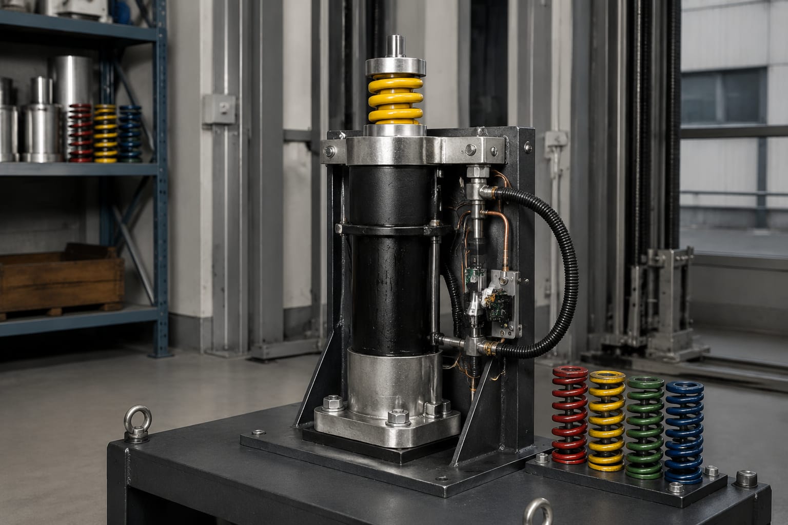
With the lift secured and the work area made safe under the site procedures, inspect for:
- Oil leakage from seals, plugs, joints, cylinder walls or damaged hoses where applicable.
- Insufficient oil level or evidence of contaminated oil in serviceable designs.
- A piston or plunger that fails to return fully, returns slowly, or is visibly scored.
- Bent, loose or misaligned buffer components.
- Spring cracks, broken coils, rubbing marks or permanent compression.
- Corrosion on cylinders, springs, base plates, fasteners and pit supports.
- Cracked concrete, damaged steelwork, loose anchors or elongated mounting holes.
- Missing labels, unreadable rating plates or evidence of an unapproved modification.
- Car or counterweight striker damage and off-centre contact marks.
- Damaged switch housings, unsecured conduits, water ingress or loose wiring.
- Debris that could obstruct compression or prevent full return.
Do not paint over heavy corrosion as a substitute for assessment. Surface treatment may be appropriate only after determining that the component remains structurally and functionally acceptable. Pitting on a piston rod or cylinder, for example, can quickly damage seals and create recurring leakage.
An oil buffer that has discharged oil, a spring buffer with broken or deformed coils, or any buffer with uncertain rating should be treated as unfit until assessed and corrected. The appropriate response will depend on the lift condition, risk assessment and applicable maintenance procedures.
Replacement identification and installation
Accurate identification avoids costly returns and, more importantly, prevents an incompatible safety component entering the shaft. Start with the existing unit, but verify it against lift data rather than relying on a single source.
Record the following before removal:
| Information to record | Why it matters |
|---|---|
| Manufacturer, model and serial or part number | Provides the strongest initial compatibility reference |
| Buffer type and data-plate rating | Confirms intended performance category |
| Rated lift speed and moving mass | Supports validation of the buffer selection |
| Effective stroke and extended height | Prevents clearance and travel errors |
| Base dimensions and fixing centres | Confirms physical installation compatibility |
| Top contact or striker dimensions | Ensures centred, stable engagement |
| Switch make, part number and wiring details | Prevents electrical mismatches |
| Clear photographs of the unit and installation | Helps identify brackets, wiring and site-specific features |
| Reason for replacement | Reveals whether a wider fault investigation is needed |
A replacement buffer should be installed on a sound, level support using the specified fasteners and torque requirements. Align it with the intended contact point before final tightening. Ensure that no packing, improvised bracket or altered striker changes the original geometry unless the modification has been properly designed and approved.
For oil buffers, follow the product-specific handling and filling instructions. Protect the piston surface during transport and installation. For spring buffers, ensure the spring assembly, guides and retaining components are complete and correctly seated.
Do not substitute a buffer switch by matching only its connector or mounting holes. The safety circuit needs the correct contact action at the correct buffer position. Similarly, do not reuse corroded fasteners or install a new buffer on a deteriorated base.
Post-service inspection and testing
Replacement work is incomplete until the entire buffer arrangement has been inspected and tested under controlled conditions. The exact test method and acceptance criteria depend on the lift type, buffer design, site rules and applicable requirements. Work should be carried out by personnel authorised and competent for lift safety work.
The post-service process should normally include:
- Confirm the installed buffer model, position, height and fixing arrangement against the approved selection.
- Verify that car and counterweight contact points align centrally with their buffers.
- Check that the buffer is fully returned and that no obstruction exists in the pit.
- Test buffer switch continuity and safety-circuit operation at the controller using the correct procedures.
- Confirm that the lift cannot operate when the buffer proving condition is not met, where the design requires this.
- Inspect final-limit devices and lower terminal stopping arrangements, since buffer contact can indicate faults elsewhere.
- Carry out the specified functional testing and record the results, including the replacement part details.
- Reinspect for leaks, loose mountings or abnormal marks after testing.
Avoid a full-speed impact test unless it is expressly required and conducted under the applicable procedure. Deliberately driving a lift onto a buffer without proper controls can damage equipment and expose people to significant risk. Controlled verification should demonstrate that the buffer is correctly installed and the safety circuit responds as intended.
For B2B buyers and maintenance teams, a good replacement request includes the original part data, lift speed, relevant mass, dimensions, photos and switch details. Kelevator supplies multi-brand lift spare parts for importers, distributors, maintenance contractors and OEM buyers; this information makes a technical compatibility review more practical and reduces reliance on appearance alone.
Related product references
For practical catalog examples related to this topic, review [Hydraulic oil pressure buffer lift parts elevator accessories](/products/hydraulic-oil-pressure-buffer-lift-parts-elevator-accessories/), [3300 3600 Elevator Buffer Switch Parts lift parts](/products/3300-3600-elevator-buffer-switch-parts-lift-parts/), and [Elevator buffer switch – – Mitsubishi lift parts](/products/elevator-buffer-switch-mitsubishi-lift-parts/). Confirm the exact model, dimensions, ratings, and connectors before ordering.