
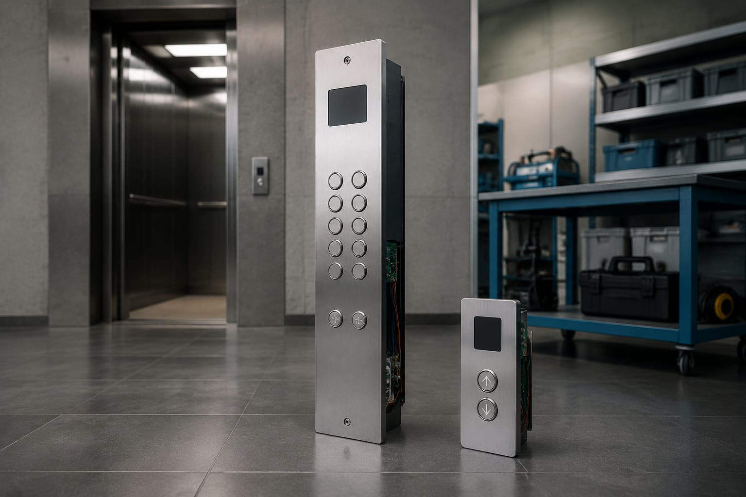
An elevator button panel is more than a set of push buttons. It is the operating interface between passengers, the lift controller and the building. Selecting or replacing one requires the right panel type, button layout, faceplate dimensions, wiring and communication compatibility.
The two main types are the car operating panel (COP) inside the lift car and the landing operating panel (LOP) at each floor. They serve different functions, but both must match the lift’s controller, installation conditions and required accessibility features. For maintenance contractors and sourcing teams, checking the existing panel before ordering is usually more reliable than matching only by appearance or lift brand.
COP and LOP explained
A COP is fitted inside the elevator car. It lets passengers select floors and access car-specific functions such as door open, door close, alarm and emergency communication. It may also contain a position indicator, overload message, key switch, emergency lighting controls or an inspection-related function, depending on the lift design.
A LOP is installed outside the lift, normally beside the landing door. Its primary job is to register a passenger’s call. In a conventional collective-control system, a middle-floor LOP generally has separate up and down buttons; terminal landings may have one direction button only.
| Feature | Car operating panel (COP) | Landing operating panel (LOP) |
|---|---|---|
| Location | Inside the elevator car | At each landing |
| Main purpose | Destination selection and in-car functions | Calling the elevator to a floor |
| Typical controls | Floor buttons, door controls, alarm, emergency call | Up/down call buttons, destination keypad or access reader where used |
| Typical displays | Car position, direction, overload or status messages | Position, direction, arrival signal or destination-control information |
| Compatibility focus | Car layout, controller input/output, car-top and travelling cable connections | Landing box dimensions, riser wiring, controller protocol and mounting arrangement |
| Environmental exposure | Passenger use, cleaning products and vandalism risk | Public access, dust, moisture and varying building conditions |
The distinction matters during procurement. A COP replacement may need to preserve all emergency, accessibility and door-control functions, while a LOP replacement must suit its landing position and the building’s existing call wiring. A panel labelled simply as an “elevator button panel” does not establish whether it is suitable for either role.
In destination-control installations, the conventional difference becomes less clear. A landing device may include a keypad, touchscreen or card reader that assigns a lift and displays the allocated car. The car itself may have fewer floor buttons or none at all. Such systems need careful protocol and controller verification before components are changed.
Parts inside an elevator button panel
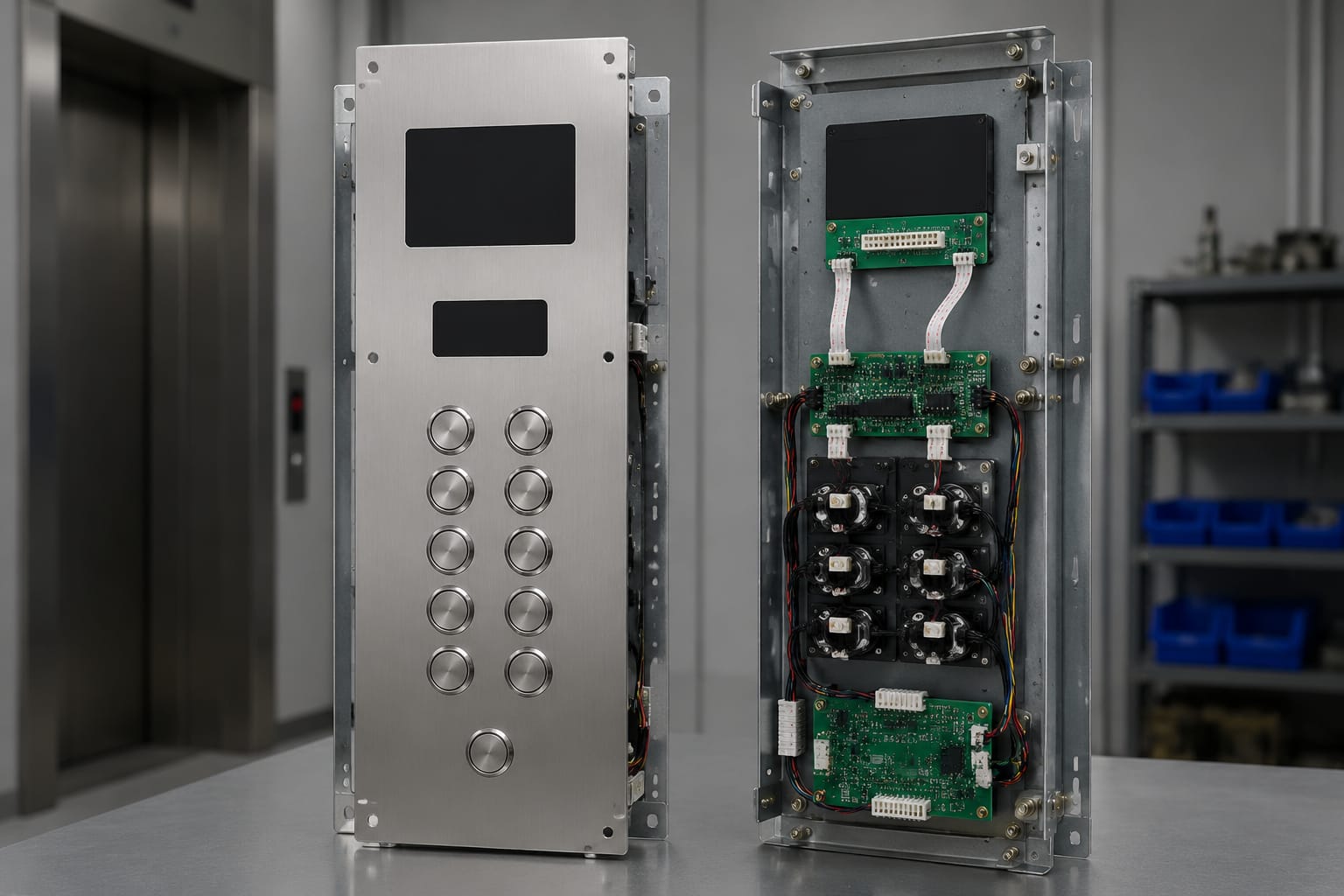
The visible faceplate is only one part of the assembly. A complete elevator panel commonly includes the following components:
- Faceplate or fascia: The front panel that carries buttons, displays, symbols, apertures and engraved information.
- Push buttons: Mechanical, capacitive or touchless controls with legends, illumination and contact arrangements appropriate to the lift system.
- Button modules and retainers: The housings, clips or fixing hardware that secure each button to the faceplate.
- Indicators: Illumination confirming a call or selected floor. These may be integrated into the button or fitted separately.
- Position and direction display: A dot-matrix, segment, LCD or other display showing car position, travel direction or operational messages.
- Audio components: Arrival gongs, buzzers, speakers or voice-announcement interfaces where specified.
- Control board: A printed circuit board (PCB) that reads button inputs, manages illumination and communicates with the main controller.
- Wiring harness or connection cable: The cable assembly connecting the panel to the car operating station, landing network or lift controller.
- Connectors and terminals: The plugs, pins, sockets or terminal blocks that establish electrical and data connections.
- Emergency and access devices: Alarm buttons, intercom units, key switches, card readers, fire-service controls or other building-specific equipment.
A fault in any one of these components can resemble a button fault. For example, several unresponsive buttons may indicate a shared supply, connector, cable core or board problem rather than failed individual buttons. Equally, replacing a whole panel because one indicator lamp has failed can add cost and introduce unnecessary compatibility risk.
When assessing a repair, establish whether the issue is cosmetic, mechanical, electrical or communication-related. A scratched fascia may only require a faceplate replacement. A loose button may need a retainer or button module. A blank display may involve the display itself, its power supply, its data connection or a configuration issue at the controller.
Button and display configurations
Panel configuration should reflect the building, passenger flow and controller capabilities. The common arrangement is a one-car or two-car collective system with individual floor buttons in the COP and direction buttons at each landing. Yet even this straightforward arrangement varies considerably.
Buttons
Floor buttons may use numerals, letters, basement designations, parking levels or mixed labels. Confirm the exact legends, including any roof, service, mezzanine, ground, parking or restricted levels. A floor number that looks similar can still be incorrect for the building’s wayfinding system.
Other common COP buttons include:
- Door open and door close controls
- Alarm or emergency-call button
- Fan or light controls in older installations
- Key-operated service, independent or restricted-access controls
- Fire-service controls where applicable
- Emergency stop functions in specific lift types or older configurations
A LOP may have one call button, separate up and down buttons, an arrival indicator, or a more advanced destination-entry interface. Direction arrows and colours should be clear and consistent throughout the site. Do not assume that any illuminated call button will work with the existing board: voltage, signal method, lamp type, common wiring and mounting geometry can all differ.
Displays and indicators
Displays range from simple arrow-and-floor indicators to LCD panels that show destination, messages and status information. The choice should consider viewing distance, ambient light, angle of view, power requirements and controller compatibility.
An LCD landing display can improve legibility and support more detailed passenger information, but it may require a compatible communication interface rather than straightforward discrete wiring. For projects using this format, review the available outbound-call LCD panel options against the controller and installation requirements before specifying them.
A useful replacement brief records:
- Button type, shape, diameter or cut-out size.
- Button legend and illumination colour.
- Number and arrangement of buttons.
- Display type, visible area and mounting cut-out.
- Required symbols, arrows, Braille or tactile markings.
- Existing board part number and connector details.
- Whether the panel uses conventional inputs or serial communication.
Faceplate materials and dimensions
Faceplates influence durability, cleaning, appearance and installation fit. Stainless steel is widely used because it is robust, corrosion-resistant and suitable for high-traffic environments. Brushed, patterned or mirror finishes each show fingerprints and scratches differently, so the selected finish should suit the building’s maintenance expectations.
Other materials may include painted steel, aluminium, glass, acrylic or composite finishes. These can suit a particular design scheme, but the decision should account for impact resistance, fire-performance requirements, cleaning methods, edge protection and the ability to replace damaged parts later.
Dimensions are equally important. Measure the complete faceplate, not just the visible opening. Record:
- Overall height, width and thickness
- Fixing-hole positions, quantity and screw type
- Button and display cut-out dimensions
- Distance between cut-outs and panel edges
- Back-box or recess dimensions for LOPs
- Available depth behind the faceplate
- Position of cable-entry points and connector clearance
A panel can have the correct overall height and width but still fail to fit because its fixing centres, cut-outs or rear clearance differ. For a COP, confirm that the new fascia will not interfere with handrails, mirrors, grab bars, car walls or existing emergency equipment. For a LOP, check the landing wall finish and back-box condition before committing to a flush-mounted replacement.
Where an existing panel is being retained, a custom faceplate can be a practical modernisation option. However, every aperture should be matched to the actual component selected, including its locking method and depth. Avoid ordering a blank or pre-punched plate based solely on a photo.
Board, cable, and connector matching
The board, cable and connector arrangement is the most important compatibility area when replacing an elevator button panel. Similar-looking buttons and panels can use different input methods, voltages, pin assignments or protocols. A direct physical fit does not prove electrical compatibility.
What to match before ordering
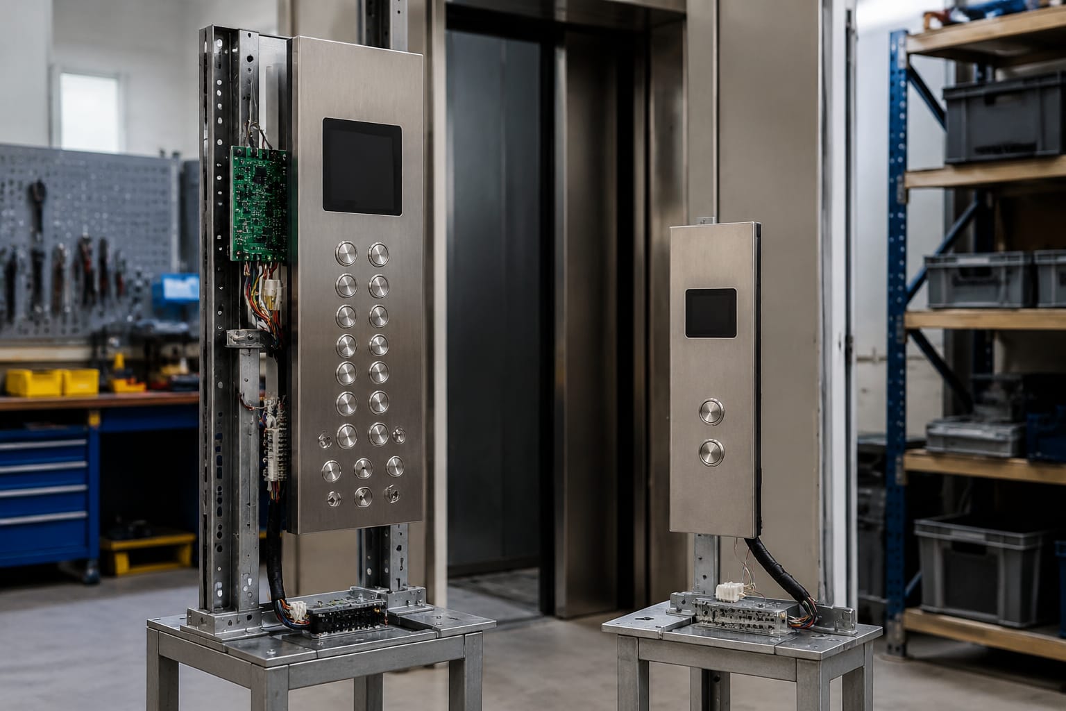
Start with the installed panel and controller documentation where available. Capture clear photographs of both sides of the panel, label every connector and record all readable part numbers. Then verify:
- Board manufacturer and part number
- Lift controller make, model and software or system generation where relevant
- Number of button inputs and output channels
- Supply voltage and polarity
- Connector type, pin count, keying and pin-out
- Cable length, conductor count, shielding and termination style
- Communication type, where the panel uses a bus or serial network
- Addressing, programming or configuration method
- Display and button illumination requirements
A ten-pin cable is not automatically interchangeable with another ten-pin cable. Pin numbering, connector gender, key position, core allocation and voltage assignment must all be checked. For compatible replacement planning, compare the existing assembly with the specifications of a 10-pin COP/LOP connection cable rather than relying on pin count alone.
Common matching mistakes
The most frequent procurement errors are avoidable:
- Ordering by lift brand without confirming the controller family and panel part number.
- Matching a connector from its front view but overlooking keying or pin orientation.
- Reusing an old cable whose pins are loose, corroded or damaged.
- Assuming all LEDs, lamps and displays use the same operating voltage.
- Replacing a board without checking whether it needs addressing or parameter configuration.
- Combining components from different systems without confirming the signal method.
- Cutting a new faceplate before the final button and display modules have been physically checked.
When a board is obsolete, a compatible replacement may require a harness adapter, revised button modules or controller configuration. Treat this as a system-level change, not a simple PCB substitution. A matching elevator control-panel button board can be useful for replacement sourcing, but its exact application should still be validated against the installed panel and controller.
Accessibility and emergency controls
COP and LOP layouts should support clear, reliable use by a broad range of passengers. Practical accessibility features often include tactile floor legends, Braille markings, distinguishable button shapes, visual confirmation, audible arrival signals and readable position indicators. The required arrangement depends on the building, lift specification and applicable project requirements, so confirm these before finalising the panel design.
Buttons must be positioned where passengers can reach them comfortably. Their labels should remain legible under normal lighting, while indicator illumination should be visible without creating glare. High-contrast legends and clear directional arrows reduce ambiguity, particularly in busy public buildings.
Emergency controls require particular care because they form part of the lift’s safety and communication arrangements. Depending on the installation, this may include an alarm button, two-way communication device, emergency call interface, key switches or status indications. Replacement work must preserve the intended function and must not leave emergency devices disconnected, obscured or incorrectly labelled.
Do not treat a red button as proof of a correctly integrated emergency system. Confirm its contact type, wiring, monitoring method and relationship to the lift controller or communication equipment. Any work affecting emergency functions should be tested by competent personnel as part of commissioning.
Customization and modernization options
Modernising an elevator button panel can improve appearance, usability and component support without replacing the entire lift. The appropriate scope depends on the age of the controller, the condition of the wiring and the project objective.
Common options include:
- Replacing worn faceplates while retaining compatible buttons and boards
- Updating buttons to improve tactile feedback, illumination or legibility
- Adding or replacing position and direction displays
- Revising floor legends following a building layout change
- Integrating access-control readers or key switches
- Upgrading landing call stations for a consistent building finish
- Introducing destination-control interfaces where the wider system supports them
- Replacing damaged harnesses, connectors or button boards as part of a targeted repair
A cosmetic upgrade can become a technical upgrade quickly. For example, changing from conventional button lamps to illuminated button modules may alter the required supply and board outputs. Changing a basic indicator to an LCD may require a data connection, programming and a compatible controller interface.
For staged modernisation, begin with a condition survey. Separate components that are visibly worn from components that are electrically unreliable or obsolete. This helps determine whether a new faceplate and buttons are sufficient, or whether the job should include boards, cables and controller-side work.
For B2B sourcing, Kelevator supplies multi-brand elevator spare parts to importers, distributors, maintenance contractors and OEM buyers. A practical enquiry should include panel photographs, measurements, part numbers, connector images and the intended application. That information reduces the chance of selecting visually similar but incompatible parts.
Panel testing and commissioning
A replacement panel should be tested as an assembly, then commissioned within the lift system. Bench testing can identify obvious issues before fitting, but it does not replace operational checks after installation.
Pre-installation checks
Before mounting the panel:
- Inspect the faceplate, buttons, display, board and cable for damage.
- Confirm every connector, pin count and keyway against the recorded installation details.
- Check button legends and floor sequence against the building’s actual levels.
- Verify that fixing hardware, earthing arrangements and apertures are correct.
- Confirm whether the board or display needs addressing, configuration or firmware matching.
- Check that cable routing will not trap, strain or abrade conductors.
Functional commissioning checks
After installation, test the complete passenger interface and associated lift response. At minimum, verify:
- Every COP floor call registers, illuminates and takes the car to the correct level.
- Door open and close controls operate as intended.
- LOP direction calls register and are cleared correctly after service.
- Position, direction and arrival indications are accurate.
- Audible signals and voice functions work where fitted.
- Restricted floors, key switches and access-control functions behave as specified.
- Emergency alarm and communication functions are operational.
- Panel illumination, display readability and tactile markings are suitable in normal site conditions.
- No intermittent faults occur when cables or connectors are in their installed positions.
Keep a record of the installed part numbers, cable connections, configuration settings and test results. This makes future fault-finding faster and supports consistent maintenance, especially where identical lifts have different panel revisions.
A well-matched elevator button panel preserves dependable lift operation while improving the passenger experience. Before replacing a COP or LOP, identify the exact function, document the mechanical dimensions, and verify the board, cable and connector arrangement. That approach is more dependable than selecting components by appearance alone and gives maintenance teams a clear basis for repair or modernisation decisions.
Related product references
For practical catalog examples related to this topic, review [Elevator Control Panel Button Board lift accessories](/products/elevator-control-panel-button-board-lift-accessories/), [3300 3600 5500 LOP COP Control Panel Connection Cable 10 Pin Core lift accessories](/products/3300-3600-5500-lop-cop-control-panel-connection-cable-10-pin-core-lift-accessories/), and [Outbound call LCD panel STEP system elevator parts](/products/outbound-call-lcd-panel-step-system-elevator-parts/). Confirm the exact model, dimensions, ratings, and connectors before ordering.