
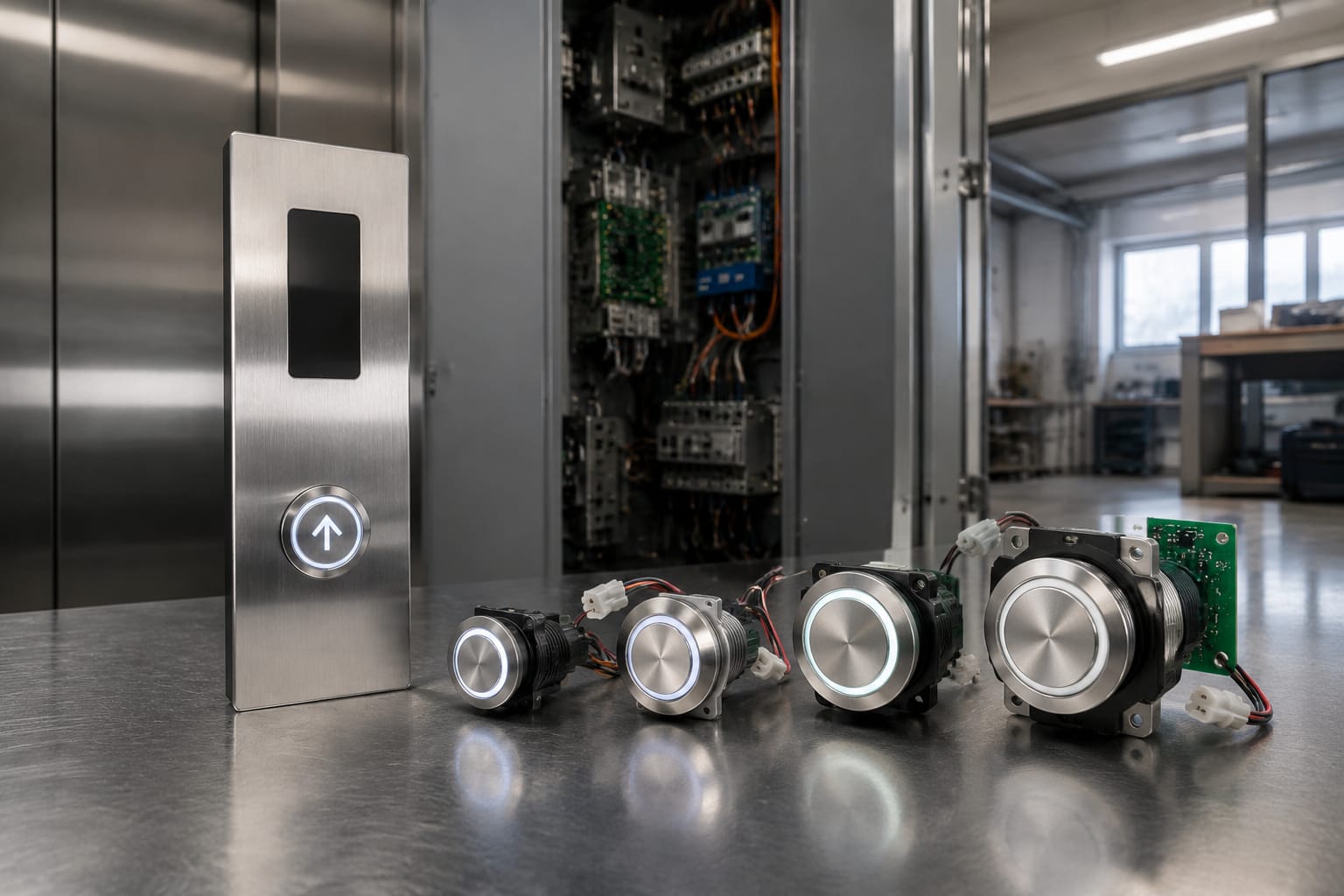
Elevator buttons replacement is rarely just a matter of fitting a new push button into the same hole. A button may look correct yet be incompatible with the existing operating panel because its mounting depth, contact arrangement, supply voltage, illumination type or connector differs. The fault may also be in the button board or wiring rather than the button itself.
For a reliable repair, first isolate and diagnose the fault, record the existing part’s physical and electrical details, then verify operation after installation. This approach reduces repeat call-outs, prevents damage to the panel, and helps maintenance teams decide whether an individual button or a wider panel repair makes better commercial sense.
When an elevator button needs replacement
Replace an elevator button when inspection and testing show that the button itself is defective, damaged or no longer suitable for safe, dependable passenger use. Common signs include a button that does not register a call, remains permanently lit, sticks in or sits loose in the faceplate, has a cracked legend, or has damaged contacts or terminals.
Appearance alone is not enough to confirm the cause. A dark button may have a failed lamp or LED, but it could also have no supply from the panel. Likewise, an intermittent response can result from a worn switch mechanism, a loose connector, a fractured conductor or an input fault on the controller interface.
A replacement is generally warranted when one or more of the following applies:
- The button does not change state when electrically tested.
- The mechanical action is inconsistent, rough or does not return properly.
- The cap, Braille marking, legend or illuminated ring is damaged or unreadable.
- Terminals, pins or the rear housing are damaged.
- The button has water ingress, heat damage or corrosion.
- An approved compatible replacement is needed during a panel refresh or lift modernisation.
Where a button has been vandalised or repeatedly fails in the same position, investigate the underlying condition before ordering several replacements. Misalignment, excessive panel flex, moisture, a strained harness or unsuitable cleaning products can shorten the life of a new button as well.
Before accessing the panel, authorised personnel should place the lift in an appropriate maintenance condition, isolate relevant supplies according to the site procedure, and prevent the lift from being returned to normal service until the work is complete. Panel work can affect safety circuits and live electrical equipment; it belongs with competent lift technicians.
Diagnose the button, board, or wiring
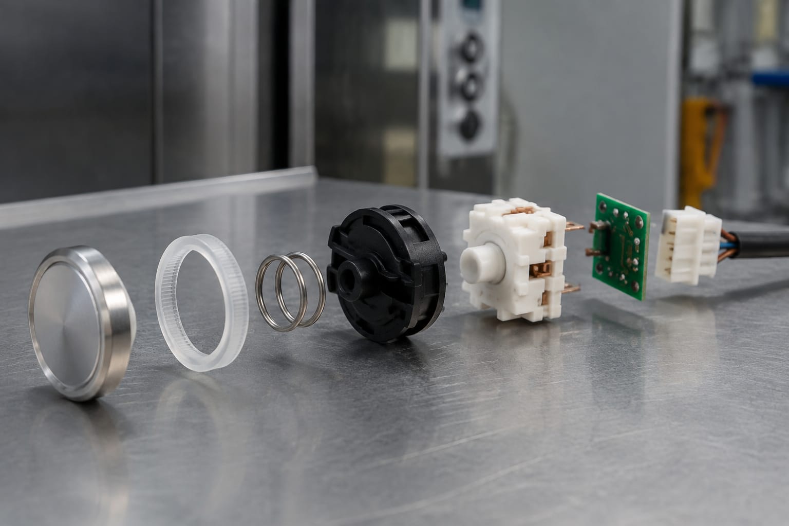
The goal of diagnosis is to identify the failed layer before parts are ordered. In a typical car operating panel, the passenger button is only one part of a chain: the button mechanism, illumination circuit, connector or terminals, harness, input/output board, controller logic and associated configuration can all affect the result.
Start with the simplest observations. Compare the suspect button to a known working button of the same type. Check whether the cap moves freely, whether the illumination behaviour matches nearby buttons, and whether a loose panel or damaged cable is visible. Record the symptoms before disconnecting anything.
A practical fault-isolation sequence
- Confirm the symptom. Note whether the issue is no response, intermittent registration, constant registration, failed illumination, incorrect colour, or an incorrect floor function.
- Inspect the mechanical condition. Look for a displaced button, cracked bezel, contamination around the cap, damaged retaining hardware, bent pins or a partially seated plug.
- Check the panel connection. With power isolated where required, inspect the connector, harness strain relief and terminal condition. Reseat connections only where the applicable maintenance procedure permits it.
- Test the switch and illumination circuit. Use suitable test equipment and the relevant wiring information to check contact operation and, separately, the lighting circuit. Do not infer a failed switch solely from a failed lamp.
- Compare at the board input. If the button tests correctly but the controller does not see the command, trace the signal through the harness and button board. A shared failure affecting several buttons points more readily to a common board, supply or wiring issue.
- Check the programmed or configured function. On systems where inputs are assigned electronically, a correct physical button may still need the correct configuration. This is especially relevant after panel or controller work.
Fault patterns that help narrow the cause
| Symptom | Likely areas to inspect | Important limitation |
|---|---|---|
| One button has no response and no illumination | Button, local connector, local harness branch | A supply or board fault can still affect only one channel |
| One button responds but does not light | LED/lamp circuit, polarity, illumination supply | The button may be mechanically sound |
| Several adjacent buttons fail together | Shared connector, harness, board, common supply | Do not replace all buttons before checking the common path |
| Button is permanently active | Stuck mechanism, shorted switch, damaged wiring, input fault | A mechanical jam and an electrical short can produce similar behaviour |
| Button works intermittently | Loose plug, fractured conductor, panel movement, worn contact | Test under controlled conditions; a static test may miss an intermittent fault |
| All panel buttons are unresponsive | Panel supply, communications, board, controller state | This is unlikely to be solved by replacing individual buttons |
For boards that serve several car buttons, it may be useful to compare connector layout, input count, supply requirements and system family before replacement. Kelevator supplies multi-brand lift spare parts for B2B buyers, and its [elevator car button boards](/products/elevator-car-button-board-lift-parts/) illustrate the type of component that should be assessed when the button itself proves sound.
Record dimensions and mounting style
A clear part record is more valuable than a vague description such as “round Otis button” or “27 mm lift button”. Similar-looking push buttons can differ in cut-out size, outside diameter, body depth, panel thickness range, anti-rotation feature, fixing method and rear clearance.
Take measurements from the removed part where possible, not only from the panel opening. Photograph the front, rear, label and connection points in good light. Include a scale in at least one photo, but do not use a photograph as the sole source of a critical dimension.
Record these details before seeking a replacement:
- Manufacturer name, part number, revision and any markings on the body or cable.
- Car operating panel position and function: floor selection, door open, door close, alarm, emergency call or other command.
- External shape and finish: round, square, rectangular or other form; flush or raised profile; stainless, chrome, black or another finish.
- Panel cut-out diameter or width and height, plus outside bezel dimensions.
- Body depth behind the faceplate and available clearance inside the panel.
- Panel thickness and fastening method, such as threaded collar, retaining clip, nut, screws or a rear-mounted bracket.
- Anti-rotation tab, flat edge, locating pin or keyed opening.
- Legend, floor designation, arrows, symbols, tactile marking and Braille arrangement.
- Connection type: loose wires, screw terminals, spade terminals, plug, pin header or a dedicated harness.
- Number of pins or contacts and their position.
- Existing button colour and illumination behaviour.
Do not enlarge or alter the panel cut-out simply to accept an available button until the impact on fit, panel strength, finish and future servicing has been considered. A modified opening may make it difficult to source a clean replacement later, and it can leave a visible mismatch around the bezel.
A product described by its hole size should still be checked against all other dimensions. For example, a [27 mm open-hole, four-pin green-light lift button](/products/button-4-pins-open-hole-27mm-green-light-otis-elevator-parts-lift-accessories/) is relevant only where the original part’s mounting and electrical arrangement match. The nominal size and a familiar brand reference alone do not establish compatibility.
Match voltage, illumination, and connector
Electrical compatibility is as important as physical fit. Confirm the replacement’s operating details against the existing button, wiring diagram, panel documentation or validated readings from the equipment. Never assume that two buttons with the same cap size use the same voltage, pinout or LED arrangement.
Electrical details to verify
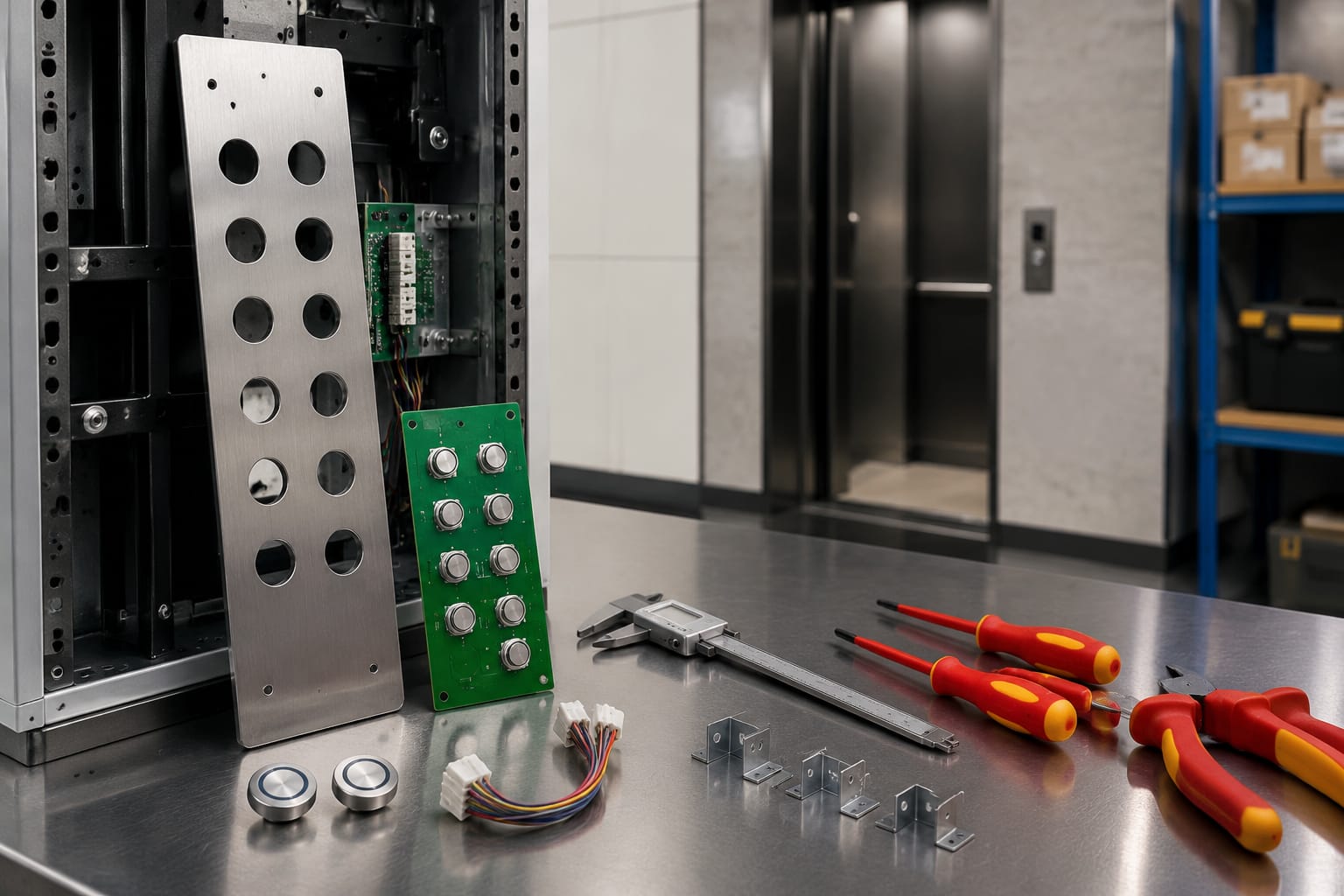
Switch contacts: Establish whether the button uses normally open, normally closed or another contact arrangement, and whether it is momentary or latching. A lift button that must momentarily signal a board cannot safely be substituted with a mechanically different type merely because the terminals appear similar.
Voltage and current: Confirm the circuit’s voltage type and rating, including whether the illumination is supplied separately from the switch signal. AC and DC systems, nominal voltage values and allowable tolerances vary by design. Use the equipment documentation and the exact part marking.
Illumination: Check whether the original uses an LED, lamp, illuminated ring, backlit legend or a separate indicator. Verify colour, polarity where relevant, brightness expectations and whether illumination is controlled locally or by the board. A replacement may switch correctly yet provide the wrong indication if its lighting circuit differs.
Connector and pinout: Count pins, identify connector family, note keying and compare the order of functions. A four-pin button is not automatically interchangeable with another four-pin button. Pins may serve different arrangements of switch common, switch output, LED positive and LED negative.
Signal type: Some panels use simple dry contacts; others use board-specific inputs, multiplexed arrangements or dedicated assemblies. Do not attempt to adapt an unfamiliar electronic button without confirmed documentation. An improvised adapter can introduce unreliable joints, reverse polarity or damage sensitive inputs.
Function and marking: The visible face must correspond to the actual command. Floor labels, direction arrows, door symbols and emergency functions should not be casually exchanged. Where tactile information is present, retain the intended orientation and legibility.
It is sensible to compare both a working adjacent button and the suspect original. The adjacent comparison can reveal a standard panel family; the original part preserves the exact mounting and connector information for the failed position.
What affects replacement cost
The cost of elevator buttons replacement consists of more than the purchase price of the component. For budgeting, separate the part cost from diagnosis, access, installation, testing, documentation and any wider repair found during fault isolation.
The main cost drivers are:
| Cost factor | Why it changes the total |
|---|---|
| Button type and construction | Standard mechanical push buttons are generally simpler to source than specialised, vandal-resistant, custom-marked or electronically integrated parts |
| Compatibility certainty | Incomplete records may require extra diagnosis, comparison or samples before a suitable part can be selected |
| Quantity | Replacing one item may cost less in materials, while a planned set can reduce repeat attendance and visual inconsistency |
| Panel condition | Damaged cut-outs, corroded fixings, brittle harnesses or poor access can add labour |
| Board or wiring faults | A sound button will not resolve a failed interface board, connector or harness |
| Illumination and legends | Special colours, symbols, tactile faces and non-standard mounting can reduce interchangeable options |
| Site access and downtime planning | Controlled access, lift isolation, return visits and commissioning affect labour and operational disruption |
| Testing requirements | A panel needs functional checks after work, particularly where control, indication or accessibility features are affected |
Avoid presenting a generic rand figure as a reliable estimate. The same symptom can be resolved by a straightforward button exchange or require board-level fault finding. A useful quote or internal purchase request identifies the exact part, quantity, panel location, required markings, electrical details and whether the diagnosis has already confirmed the button as faulty.
For importers and distributors, landed cost and continuity also matter. Confirm the manufacturer reference, revision, packaging quantity, country-specific markings where applicable, and whether the supplied item is the exact assembly or only a component that needs additional hardware. These details reduce the risk of a low unit price becoming an expensive incorrect order.
Replace individual buttons or the panel?
Replace an individual button when the fault is isolated to that button and a matching compatible part is available. This is usually the least disruptive approach and preserves a panel that is otherwise functioning and presentable.
Consider a grouped replacement or panel upgrade when buttons are visibly mismatched, several mechanisms are worn, parts are obsolete, the panel has physical damage, or the failure is tied to a board or wiring assembly rather than individual switches. The correct scope should be determined by condition, compatibility and lifecycle cost, not by the desire to replace the most parts.
Individual replacement is usually suitable when
- One button has a confirmed mechanical, contact or illumination failure.
- The original style, tactile marking, lighting and connection can be matched.
- Other buttons are operating consistently.
- The panel cut-out and harness are in good condition.
- A single replacement will not create a problematic visual or functional inconsistency.
A wider intervention may be better when
- Multiple buttons have intermittent or mechanical faults.
- The same fault returns after buttons have been replaced.
- Several buttons share a board or connector fault.
- The original parts cannot be sourced with acceptable fit and function.
- The faceplate is damaged or the panel layout needs planned modernisation.
- An individual replacement would create a different user interface, lighting colour or tactile treatment that is unsuitable for the car.
A board fault should be handled as a board fault. For example, a [Monarch-system button board expansion board](/products/button-board-expansion-board-monarch-system-elevator-parts-lift-accessories/) needs confirmation of the applicable system, connector arrangement and role in the panel before it is specified. A board that physically resembles the original can still be the wrong revision or interface.
Where several identical buttons are approaching the end of their useful life, a planned replacement set may reduce repeat work. However, retain at least one correctly identified original or an accurate part record until the replacement has been tested, so future sourcing remains traceable.
Functional and accessibility testing
A lift should not return to normal service simply because the new button illuminates or clicks. Test both the replaced button and the surrounding panel functions that could have been disturbed during access.
The exact test process depends on the lift design and site procedures, but a technician should generally confirm the following:
- The button is firmly mounted, aligned and flush enough for its intended panel design.
- The cap moves freely and returns correctly without binding against the faceplate.
- The intended call or command registers once per press.
- The button does not remain active, produce unintended calls or interfere with adjacent buttons.
- Illumination operates as intended in the relevant states.
- The visible legend, symbol, tactile marking and Braille are correctly orientated and legible.
- Door operation, alarm functions and other nearby commands remain correct where those circuits were accessed.
- Connectors, harnesses and covers are secured, with no trapped conductors or loose hardware.
- The panel is clean and free of swarf, damaged edges or fingerprints that obscure markings.
Accessibility is not an afterthought. A replacement that fits electrically but has an unclear floor marking, incorrect tactile orientation, poor contrast or inconsistent position can make the car harder to use. Preserve the original functional layout unless the work forms part of a properly specified panel upgrade.
Document the installed part number, panel location, test result and any unresolved observations. That record helps distinguish a later fault from an installation issue and makes future procurement faster.
Common ordering mistakes
Most incorrect button orders are preventable. The recurring problem is choosing by one familiar attribute while leaving the rest unverified.
Ordering by photo only. A front photo usually hides depth, retaining method, terminal layout and part markings. Always request or capture rear and side views.
Matching only the cut-out size. A 27 mm opening does not establish bezel size, anti-rotation details, depth, contacts, illumination or pinout.
Assuming the manufacturer name guarantees interchangeability. Product families and revisions can vary. Use the original part reference and compare the actual electrical and mechanical interfaces.
Ignoring the board or harness. Replacing a button without testing its path can leave the original problem untouched, particularly when several buttons share a fault.
Confusing illumination failure with switch failure. Treat the contact circuit and indicator circuit as separate checks unless documentation confirms otherwise.
Ordering the wrong face or function. Door-control symbols, emergency buttons and floor designations are not cosmetic details. Confirm the command, legend and tactile markings.
Overlooking panel clearance. A deeper replacement can foul a board, bracket, harness or panel cover even when it fits the opening.
Changing connectors without a validated pinout. Matching pin count is insufficient. An incorrectly adapted connector can cause a persistent fault or damage equipment.
Replacing a single part in a visibly inconsistent way. A different finish, lighting colour or cap profile may be technically functional but unsuitable for a passenger-facing panel.
Skipping final testing. A button can pass a bench test but fail once installed because of connector seating, panel pressure, wiring movement or system configuration.
For an efficient order, provide the original part number, clear front/rear photos, measurements, panel function, quantity, voltage and illumination information, connector and pin details, and the diagnosis already completed. Where uncertainty remains, identify it explicitly rather than treating it as confirmed compatibility.
FAQ
Can any same-size lift button replace the original?
No. The cut-out size is only one compatibility check. Confirm the mounting method, panel thickness range, depth, contact type, voltage, illumination arrangement, connector, pinout, legend and system interface.
Should a non-working illuminated button always be replaced?
No. First establish whether the switch, illumination circuit, local wiring or board is at fault. Replacing the button without diagnosis may not restore operation.
Is it better to replace all elevator buttons at once?
Not always. Replace one button when it is the confirmed isolated fault and an exact compatible match is available. Consider a set or panel-level solution when multiple parts are worn, obsolete, mismatched or connected to a common fault.
What information should a buyer send when requesting a replacement?
Send the original part number and markings, front/rear/side photographs, dimensions, panel location and function, voltage and lighting details, connector photos, pin count, quantity, and the fault diagnosis. This allows a meaningful compatibility assessment.
A disciplined elevator buttons replacement process starts with diagnosis and ends with documented functional testing. Kelevator can support B2B sourcing teams with multi-brand lift spare parts when they provide the physical, electrical and panel information needed to assess a suitable replacement.