
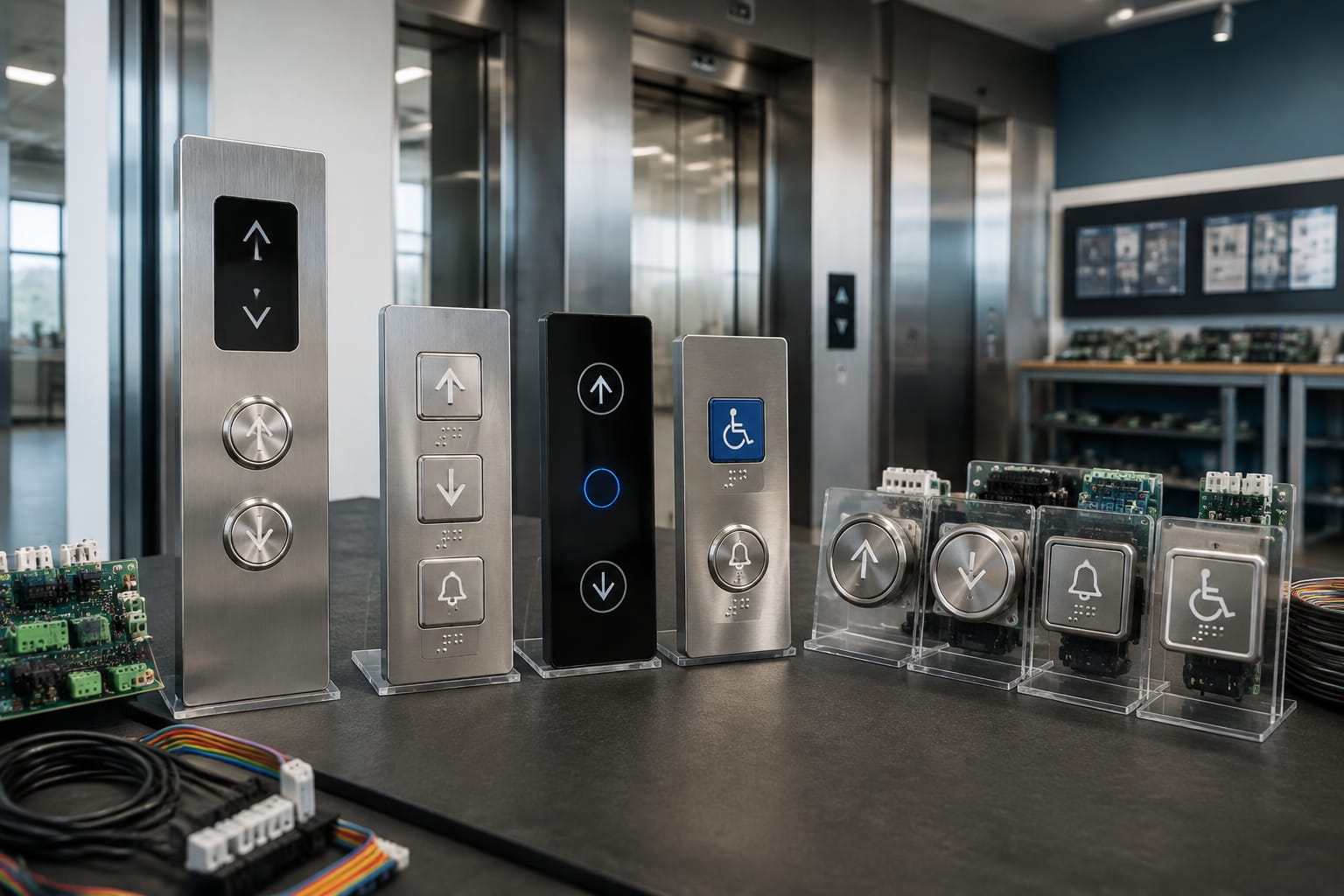
Elevator buttons are the passenger-facing controls that send a request either to the lift car controller or to the landing system. Although they may look similar, a replacement button must match the existing panel’s mounting, electrical supply, illumination method, contact arrangement and communication method.
For maintenance teams and sourcing professionals, the practical distinction is simple: car operating buttons select floors and car functions, while landing call buttons request a lift travelling in a particular direction. Correct identification before ordering prevents panel damage, repeat visits and incompatible parts.
Car operating and landing call buttons
Car operating panels are fitted inside the lift car. Their buttons allow passengers to choose a destination floor and use relevant car functions such as door open, door close, alarm and emergency communication. The panel may be called a car operating panel (COP), car station or button board.
Landing call stations are installed outside the lift car, usually at each served floor. They normally have one or two call buttons:
- An up arrow requests a lift travelling upward.
- A down arrow requests a lift travelling downward.
- A single call button may be used at a terminal floor, where only one travel direction is possible.
- Destination-control buildings may use a keypad, touchscreen or card reader instead of conventional up and down call buttons.
The function of a button is determined by the controller logic as well as its printed or engraved symbol. A round button marked “3”, for example, is not automatically interchangeable with another floor button merely because the diameter matches. The voltage, wiring and data protocol may differ.
Car buttons: what they normally control
A conventional lift car panel commonly includes:
- Floor selection buttons, marked with floor numbers or labels.
- Door open and door close buttons.
- Alarm or emergency call controls.
- An emergency stop control in systems where it is required or specified.
- Fire service, access-control or attendant controls where applicable.
- Indicators such as overload, out-of-service or emergency communication status.
Floor labels need careful checking during modernisation. A panel might use G for ground floor, B for basement, P for parking, or building-specific labels. The replacement legend should match the site’s current floor naming and not an assumed numbering sequence.
Landing buttons: what they normally control
Landing buttons are usually more straightforward, but their physical and electrical requirements still vary. A call station can use a conventional microswitch contact, a vandal-resistant metal push button, a capacitive sensor or an electronic board.
Before replacing a landing button, confirm whether the call station has:
- Separate up and down inputs.
- A shared common connection.
- An integrated LED or halo illumination.
- A replaceable button module or a complete electronic board.
- A serial connection to the controller rather than individual button wiring.
- An access-control function, such as key-switch or card-reader release.
Common elevator button symbols
Lift symbols should communicate a function quickly, particularly in an emergency or when a passenger cannot read a local language easily. The symbol, tactile marking, backlight and placement all contribute to usability.
| Symbol or marking | Usual function | Important check |
|---|---|---|
| Floor number or letter | Selects a car destination | Confirm the exact legend, character height and tactile requirement |
| Up arrow | Requests an upward journey from a landing | Usually used only where an upward journey is possible |
| Down arrow | Requests a downward journey from a landing | Usually used only where a downward journey is possible |
| Arrows pointing apart | Door open | Check the symbol orientation and controller input |
| Arrows pointing together | Door close | Do not assume it is required on every installation |
| Bell or alarm symbol | Alarm or emergency call request | Confirm whether it is a momentary input, key switch or integrated communication device |
| Phone symbol | Emergency communication | Often part of a separate emergency telephone system |
| Star, main-exit mark or special floor label | Identifies a designated exit floor | Confirm building convention and any applicable accessibility requirement |
| Fire service marking | Firefighter or fire-service operation | Use only the exact approved device and legend for that system |
Symbols alone do not establish compliance or compatibility. For example, an alarm button may be a simple dry contact in one installation and a component of a supervised emergency communication arrangement in another.
Avoid changing legends casually during repairs. A mismatched door-control symbol, incorrect floor designation or omitted tactile identifier can confuse users and create an avoidable snag during handover or inspection.
Mechanical, touch, and capacitive designs
The main elevator button types differ in how they detect an input and how they tolerate frequent public use.
Mechanical push buttons
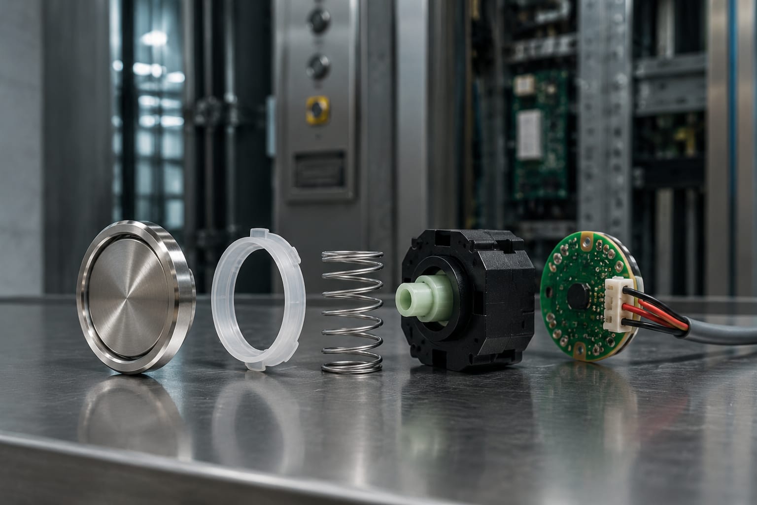
Mechanical buttons move when pressed and operate a switch, microswitch or contact block. They are common in existing lift installations because they are intuitive, serviceable and available in many shapes.
Typical features include:
- A positive press feel and audible or tactile click.
- Replaceable contact blocks on some models.
- Plastic, stainless steel or metal button faces.
- Separate lamp, LED or illuminated ring components on older designs.
- A requirement for sufficient rear-panel depth and access for servicing.
Mechanical buttons are often suitable for straightforward refurbishment, provided the mounting cut-out, thread, bezel profile and contact configuration all match. A button that physically fits the panel may still fail electrically if it has normally open versus normally closed contacts, or if its lamp circuit is unsuitable.
Touch controls
Touch controls use a flat interface instead of a moving button. They can provide a clean visual finish and may support flexible graphics, but they require a purpose-designed control system.
Their limitations should be considered carefully:
- A flat surface offers less tactile confirmation than a mechanical button.
- Glare, moisture, gloves and surface damage can affect usability, depending on the design.
- Replacing one element may require the correct manufacturer-specific overlay, board or software configuration.
- Accessibility needs may require additional tactile or audible feedback.
A touch panel is not a direct substitute for conventional push buttons without assessing the complete car panel, controller interface and passenger-access requirements.
Capacitive buttons
Capacitive buttons detect a change in an electrical field when a finger approaches or touches the surface. They have no moving mechanical mechanism, which can reduce wear from physical movement.
However, capacitive lift controls need stable configuration and correct installation. Sensitivity can be influenced by moisture, conductive contamination, earthing, front-panel materials and nearby electronics. They also need clear feedback, such as illumination, a sound or a vibration response, so users know their selection has registered.
For public-facing lift applications, specify the intended environment. A dry, protected office lift and an exposed or heavily used transport environment place very different demands on the button assembly.
Illumination, voltage, and feedback
Illumination serves two purposes: it helps passengers locate controls, and it confirms that a call or destination selection has been accepted. Depending on the system, the light may be in the button face, around its edge, behind a symbol or on a separate indicator.
Modern LED illumination generally has a longer service life and lower power demand than older lamp arrangements, but it is not automatically interchangeable. The following characteristics must be verified:
- Rated supply voltage and whether it is AC or DC.
- Current consumption and polarity for LED assemblies.
- Lamp or LED colour.
- Whether illumination is controlled continuously, on selection, or by the panel electronics.
- Common-anode, common-cathode or separate return wiring where relevant.
- Dimming, flashing or colour-change behaviour.
- Connector type, pin order and wire length.
Do not connect an LED button directly to a supply intended for an incandescent lamp unless the button assembly is expressly designed for it. An incorrect voltage or polarity can cause immediate failure, intermittent operation or damage to an electronic input.
Feedback states that should be checked after replacement
A proper functional check goes beyond confirming that the lift moves. Test whether the button:
- Illuminates at rest when the design requires it.
- Registers a press consistently across the full button face.
- Latches or changes colour correctly after a selection.
- Clears at the correct point in the journey.
- Works with any audible or visual acknowledgement.
- Does not produce false calls when adjacent buttons are pressed.
An illuminated button that remains permanently lit may indicate more than a faulty lamp. It can point to a stuck contact, a controller input state, a damaged board output or a communication fault.
Button boards and panel communication
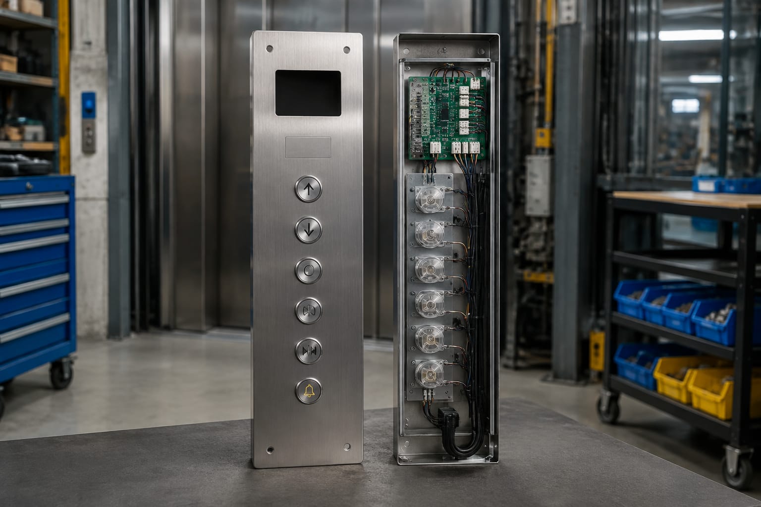
A button board connects the individual lift buttons, indicators and sometimes display elements to the lift controller. In a basic arrangement, each button may have its own wiring path. In newer or more compact installations, a board may scan inputs and communicate with the controller through a shared cable or serial bus.
This distinction is critical when sourcing parts.
Individually wired panels
In an individually wired panel, a floor button commonly provides a contact closure to an assigned controller input. The main compatibility checks are the contact type, terminal arrangement, voltage, wire identification and mounting.
These panels can make a single-button replacement relatively simple, although undocumented site modifications may complicate tracing. Photographing terminal positions and labelling conductors before removal reduces the risk of crossed connections.
Board-based and serial panels
Board-based panels use electronics to identify button presses and control lights. A fault could therefore be in the push button, the button board, the harness, a connector, the controller interface or board configuration.
When replacing a board, verify:
- Board part number and revision.
- Lift manufacturer and control system.
- Connector count, connector keying and pinout.
- Number and arrangement of button positions.
- Input/output assignments.
- Software addressing, DIP switches or configuration requirements.
- Display, buzzer, key switch and access-control connections.
For example, a Mitsubishi lift button board should be matched by its actual board identification and connection layout, not only by the brand name. Likewise, a Hyundai BD push-button board requires confirmation against the installed board before substitution.
Never assume an electronic board is plug-and-play because the connectors appear similar. Incorrect pin assignments can disable functions or damage low-voltage electronics.
Accessibility considerations
Accessible lift controls depend on the building, installation date, applicable requirements and project scope. For maintenance and modernisation work, the practical objective is to ensure controls remain perceivable, reachable and understandable for a broad range of users.
Important considerations include:
- Tactile floor markings and raised symbols where required.
- Braille information in the appropriate position and format for the panel design.
- Contrast between button legends, faces and surrounding panel material.
- Legible character size and durable markings.
- Button height, reach range and clear approach space.
- Distinct feedback through light, sound or tactile response.
- Clear identification of emergency controls and principal exit floor.
- Avoiding controls that require excessive force or very precise finger placement.
Do not add Braille labels or tactile overlays as an afterthought without checking the panel layout. Poor placement can make a panel harder to use and may obscure existing information. For a modernisation project, confirm the applicable South African building, accessibility and lift requirements with the project professional or authority responsible for the installation.
Common button failure symptoms
The symptom can help narrow down whether the fault lies in the elevator button, wiring, board or controller.
| Symptom | Likely causes to investigate | Initial check |
|---|---|---|
| Button does not respond | Failed switch, broken wire, loose connector, disabled input | Compare input response with a known working button |
| Button works only when pressed hard | Worn mechanism, misaligned bezel, contaminated switch | Inspect travel, alignment and contact condition |
| Light is off but button works | Failed LED/lamp, polarity issue, board output fault | Measure the correct supply at the button |
| Light stays on permanently | Stuck contact, incorrect wiring, controller or board state | Check contact state and compare with adjacent buttons |
| Several buttons fail together | Harness, shared supply, board or communication fault | Inspect common connectors and supply rails |
| Random calls or intermittent operation | Moisture, contamination, damaged cable, unstable capacitive sensor | Check environment, wiring and panel earthing |
| Button is physically loose | Damaged retaining nut, bezel, panel cut-out or mounting bracket | Repair mounting before replacing electrical parts |
| New button does not work | Wrong voltage, pinout, contact type or protocol | Verify the removed part and installation documentation |
A single failed button does not always justify replacing a complete panel. Conversely, repeated button failures across the same panel may make a board, harness or power investigation more economical than piecemeal replacements.
How to specify replacement buttons
A good replacement specification begins with the removed component and the installed panel, not a generic product photograph. Record enough information for a supplier or technical buyer to distinguish visually similar parts.
Minimum information to collect
Use this checklist before ordering elevator buttons:
- Lift make, controller type and panel location: car or landing.
- Clear photographs of the front, rear, terminals, connectors and panel cut-out.
- Part number, revision number and any markings on the button or board.
- Function: floor selection, up call, down call, door open, alarm or another control.
- Exact legend, symbol, floor label and language requirements.
- Button shape, diameter or dimensions, bezel style and panel thickness.
- Mounting method: threaded body, clip, screws, snap-in fitting or integrated board.
- Mechanical contact arrangement and terminal markings.
- Rated voltage, current, AC/DC supply and LED polarity where applicable.
- Illumination colour and expected operating state.
- Wiring diagram, connector pinout or board reference where available.
- Quantity required and whether adjacent buttons should match cosmetically.
For a conventional illuminated part, compare the specification against an appropriate white and blue illuminated Otis lift push button only after confirming the precise installed component. Brand compatibility is not a substitute for matching the actual part number and electrical arrangement.
Common sourcing mistakes
The most frequent replacement errors are ordering by appearance alone, overlooking the voltage, confusing a car button with a landing call button, and treating a board assembly as an individual switch. Other avoidable mistakes include ordering an incorrect floor legend, omitting the required tactile marking, and fitting a button with insufficient rear clearance inside the panel.
Where an original part is obsolete, identify which characteristics are essential and which are cosmetic. The essential items are normally controller compatibility, electrical ratings, function, mounting, reliable feedback and required accessibility features. A different bezel finish may be acceptable; an incompatible protocol is not.
FAQ
Can any elevator button be used as a replacement?
No. The replacement must be compatible with the panel cut-out, mounting depth, contact or communication method, voltage, illumination arrangement and function. For electronic panels, the board and connector arrangement also matter.
Why does a lift button light up but not register a call?
The illumination circuit and the button input circuit can fail independently. The button may have a failed contact, damaged wiring, a loose connector or an input-board fault even when the LED still operates.
Is a capacitive button better than a mechanical lift button?
Neither is universally better. Mechanical buttons provide clear physical feedback and are familiar in many existing panels. Capacitive designs offer a flush surface but need correctly designed feedback, sensitivity and environmental protection.
Should a button board be replaced when one button fails?
Not necessarily. Diagnose the individual button, its wiring and the board input first. Replace the board when testing shows a board-level fault, when multiple functions are affected, or when the assembly is not practically serviceable.
For procurement or maintenance work, document the existing button or board before removal, then match the electrical and mechanical details as carefully as the visible design. Kelevator supplies multi-brand lift spare parts for B2B buyers, including maintenance contractors, distributors, importers, modernisation teams and OEM sourcing functions.
Related product references
For practical catalog examples related to this topic, review [Push Button White Blue light OTIS elevator parts lift accessories](/products/push-button-white-blue-light-otis-elevator-parts-lift-accessories/), [button board Mitsubishi elevator parts lift accessories](/products/button-board-mitsubishi-elevator-parts-lift-accessories/), and [BD Push Button Board HYUNDAY elevator parts lift accessories](/products/bd-push-button-board-hyunday-elevator-parts-lift-accessories/). Confirm the exact model, dimensions, ratings, and connectors before ordering.