
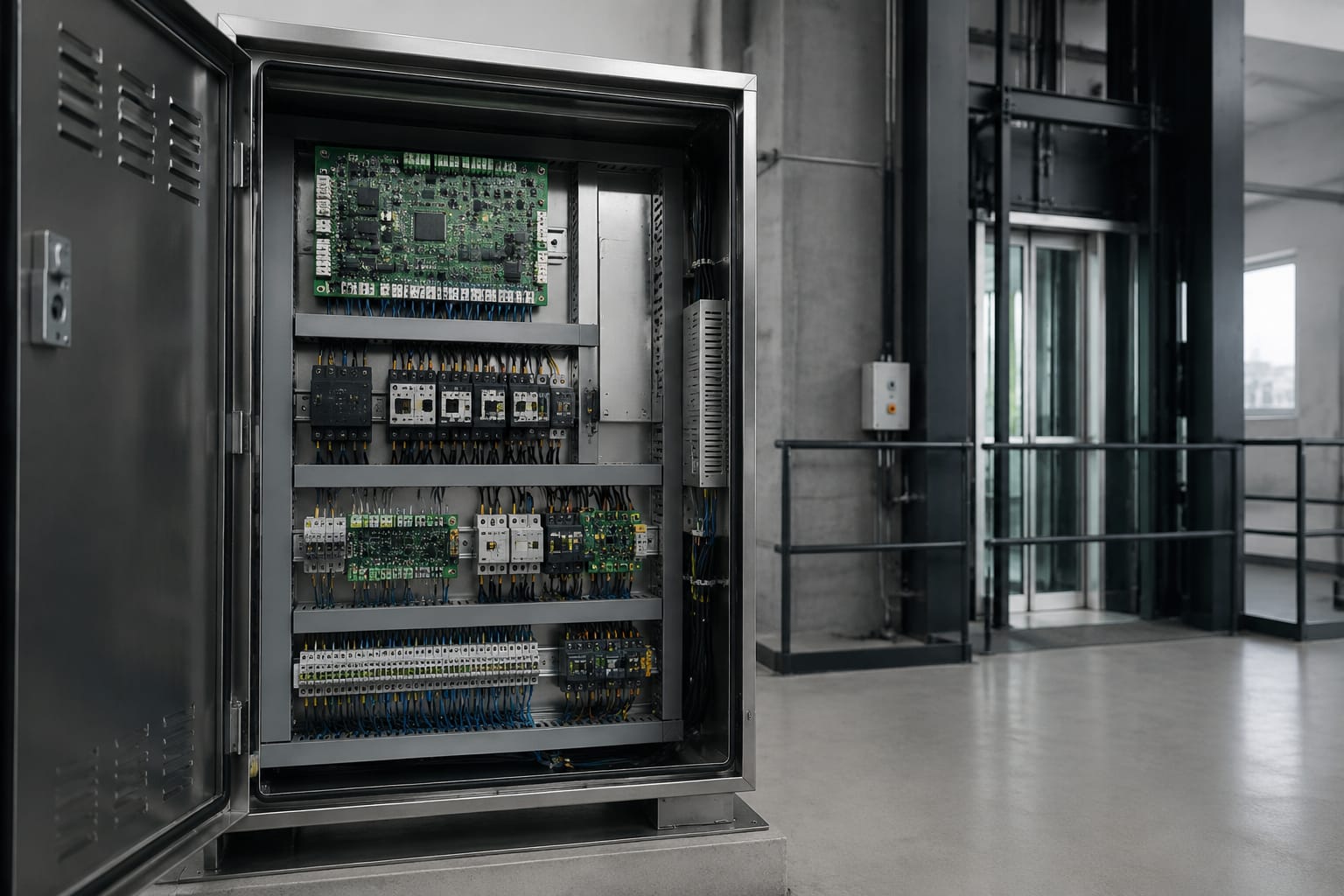
An elevator control panel is the cabinet that receives calls, monitors safety devices and commands the lift machine, doors and car functions. When it develops a fault, the visible symptom may be simple, such as a lift that will not answer a landing call, but the cause can sit in the incoming supply, safety chain, door circuit, controller board, relay logic or communications equipment.
For maintenance teams and buyers, replacing a board before identifying the failed circuit can create avoidable downtime and compatibility problems. A sound process is to record the fault, confirm the safe operating state, test the relevant inputs and outputs, and then match any replacement by exact part number, revision, supply arrangement, software and connector layout.
What an elevator control panel does
The elevator control panel, often called the lift controller or control cabinet, coordinates the equipment needed to move a car safely between floors. It continually evaluates inputs from the landing and car buttons, door equipment, position system, safety devices and machine-room components. It then drives outputs such as contactors, brake circuits, motor control interfaces, door commands, indicators and alarms.
The exact architecture differs between relay-based, microprocessor-controlled and variable-voltage variable-frequency (VVVF) installations. Yet the controller generally has four responsibilities:
- Process demand: receive car and landing calls, apply the lift’s service logic and select travel direction.
- Supervise safety: prevent movement when the monitored safety circuit, door-lock conditions or other required states are open.
- Control motion and doors: command the drive system, brake and door operator at the correct points in a journey.
- Report status: provide fault codes, indications, remote-monitoring information or voice/alarm functions where fitted.
The panel itself is not the whole lift system. A code displayed on a controller can point to a condition elsewhere, such as a door lock that does not prove closed, a failed travelling cable conductor or an intermittent machine encoder. Treat the fault record as a starting point, not proof that the controller board has failed.
In South Africa, stable supply quality and effective earthing deserve particular attention when investigating recurring electronic faults. Before assigning blame to a board, verify the panel’s supply condition, earth continuity and any surge-protection arrangement against the equipment documentation and site requirements.
Main boards and power components
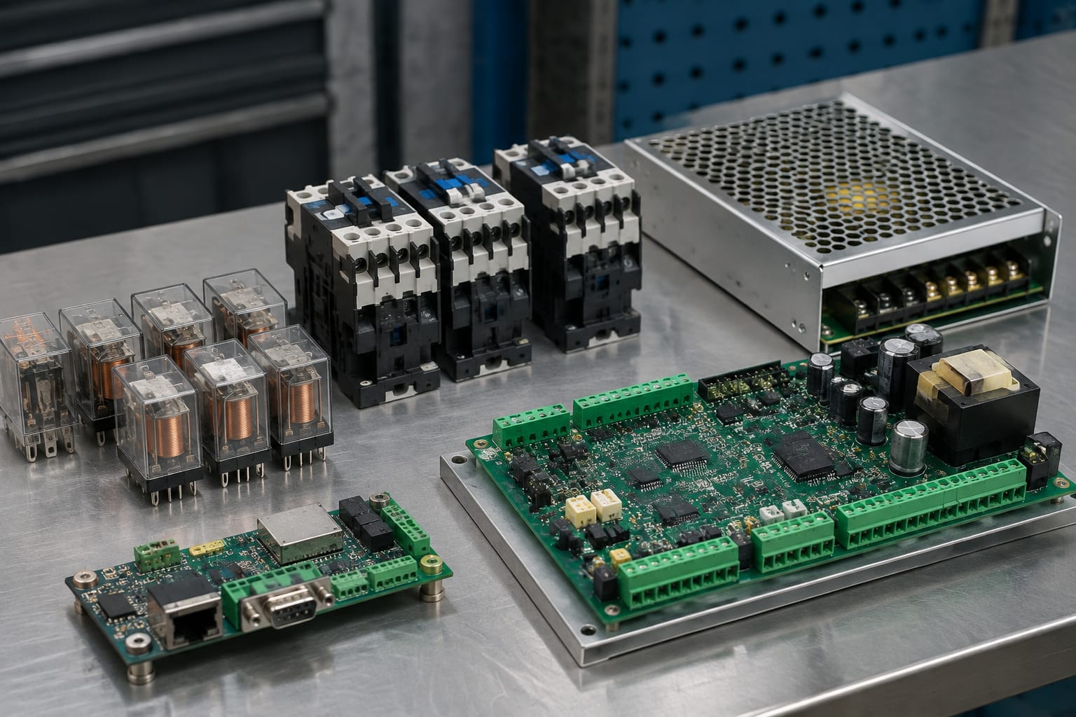
A modern elevator control panel usually combines low-voltage logic with higher-energy control circuits. Technicians should separate these functions during diagnosis because a healthy processor board cannot operate predictably with an unstable supply, and a power fault can resemble a software or communication fault.
Controller motherboard and I/O boards
The main controller board contains the processor and the lift programme. It reads essential signals directly or through input/output (I/O) expansion boards, and it issues commands to other devices. Depending on the system, boards may handle:
- Car and landing call registration
- Position, levelling and terminal signals
- Door status and door commands
- Safety-chain monitoring
- Drive and brake interface signals
- Hall indicators and car operating panel communications
- Fault logging and diagnostic access
A board should be replaced only after confirming its supply voltages, reference earth, input state and output load. For example, an output that appears dead may be protecting itself against a shorted coil or a damaged cable. Likewise, an input reported as permanently open can be caused by a field contact, not the I/O board.
For controlled replacement work, the part number, hardware revision, firmware or software version, configuration data and socketed modules all matter. Buyers assessing a [5400 elevator control motherboard and related lift accessories](/products/5400-elevator-control-motherboard-lift-accessories/) should establish those details against the existing installation rather than relying on a similar-looking board.
Power supply and protection components
Power components provide and distribute the voltages needed by the controller, relays, door circuits and related equipment. They may include isolators, fuses, circuit breakers, transformers, switched-mode power supplies, rectifiers, batteries and charging circuits.
Typical power-related symptoms include an unlit controller, repeated resets, random faults after a mains interruption, dim displays or a controller that boots but loses its configuration. Checks should include:
- Confirm incoming supply voltage and phase conditions where applicable, following the manufacturer’s procedure.
- Inspect fuses, breakers, terminals and power supply status indicators for signs of operation or damage.
- Measure the specified DC outputs under normal load, not only with plugs disconnected.
- Check battery condition and charger output where emergency functions or memory backup depend on them.
- Inspect for heat discolouration, loose terminations, moisture ingress and failed cooling arrangements.
Do not substitute a fuse rating, bypass a protective device or bridge a circuit to restore service. These actions can damage equipment or defeat a protective function, while making the original fault harder to trace.
Relays, contactors and safety circuits
Relays and contactors translate controller commands into switching actions. Relays commonly handle lower-power interlocking and signalling; contactors are used for more substantial loads, such as motor, brake or drive-related circuits, depending on the lift design.
A relay may fail mechanically, electrically or intermittently. Pitted contacts, a weak coil, poor socket contact and a damaged suppression device can all cause unreliable operation. A contactor may chatter because of an inadequate coil supply or fail to prove its state through auxiliary contacts. Replacing the contactor without identifying the cause of the abnormal condition can lead to a repeat failure.
The safety circuit requires disciplined testing
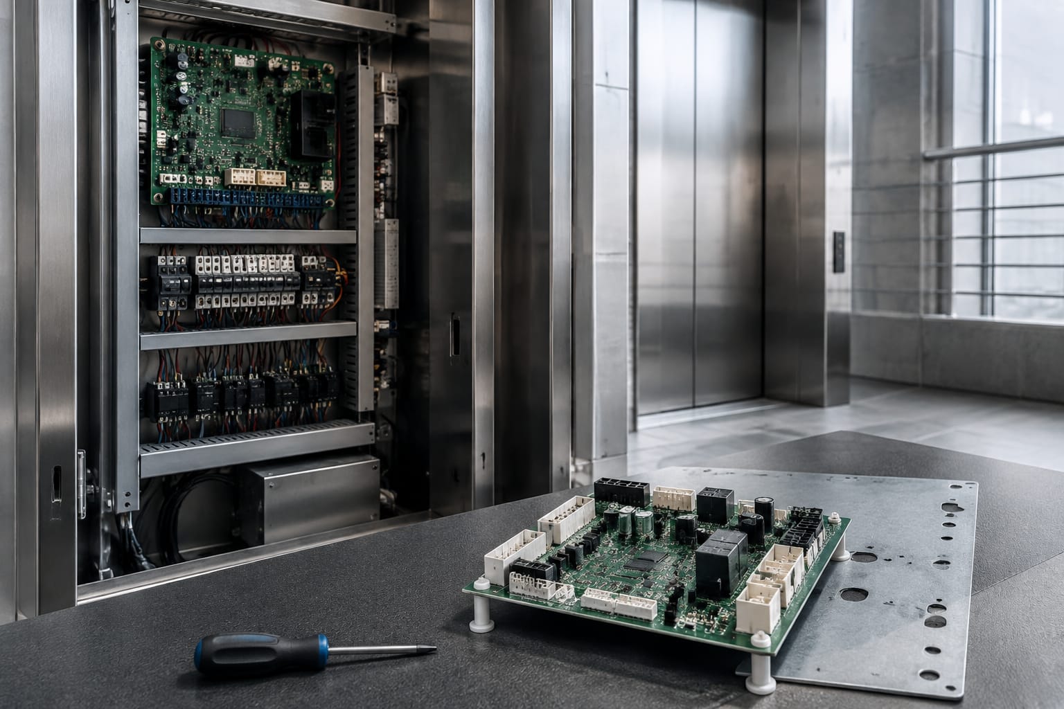
The safety circuit is a monitored series of contacts and devices that must be in the required state before movement is permitted. Its composition varies by design but can include stop switches, governor and safety-gear contacts, pit and car-top stops, door locks, inspection controls and other protective devices.
A safety-chain fault usually produces a no-run condition, but it does not identify the failed point by itself. Work methodically from the controller’s diagnostic indication and wiring diagram. Test and document each section with the equipment isolated and secured as required by the site procedure.
Common mistakes include:
- Treating a safety-chain indication as a failed controller before checking field contacts.
- Bridging a contact for longer than a controlled diagnostic test, or leaving a temporary link in place.
- Testing a door-lock circuit only at the cabinet and overlooking an intermittent landing-side connection.
- Ignoring the effect of a moving travelling cable or vibration on an intermittent fault.
Only appropriately trained, authorised personnel should work on safety circuits. The goal is to restore the intended protective function, not merely to obtain a run signal.
Communication and voice boards
Communication boards connect the controller to devices that exchange data rather than simple on/off signals. These can include car operating panels, landing stations, door controllers, displays, remote-monitoring interfaces and emergency voice equipment. The protocol, baud rate, addressing, termination and cable topology are often specific to the controller family.
A voice board may support spoken floor announcements, alarm messaging or other audible information. Before replacing it, establish whether the issue is the board, speaker, amplifier, supply, harness, configuration or audio file set. An apparent “no voice” complaint may be caused by volume settings or a failed car speaker rather than the control-panel module.
When sourcing a [3300/3600 elevator control panel voice board VCA-11-QD](/products/3300-3600-elevator-control-panel-voice-board-vca-11-qd-lift-parts/), confirm the original board marking, connector positions, system version and required programming. A matching product family name alone does not establish interchangeability.
Communication faults often present as selective failures: one floor display may be blank, one car operating panel may not register calls, or door data may drop out while the lift remains otherwise functional. These patterns are useful because they help narrow the fault to a device branch, cable section, termination or address rather than the entire controller.
Common control-panel fault symptoms
Symptoms guide diagnosis, but they are not replacement instructions. The table below maps common behaviour to likely areas for inspection.
| Symptom | Likely areas to inspect | Important limitation |
|---|---|---|
| Lift is completely dead | Incoming supply, isolator, fuses, power supply, emergency stop circuit | A dark panel may still have live incoming terminals; isolate and verify before work. |
| Controller resets or loses calls | Low-voltage supply, earth, battery, loose connectors, heat | Do not assume firmware fault until supply stability is measured under load. |
| Lift will not run and shows a safety or door condition | Safety chain, door locks, door controller, travelling cable, I/O input | The controller may be correctly reporting a field-device condition. |
| Doors repeatedly reopen or fail to close | Door operator, safety edge/light curtain, locks, door-zone signals, door I/O | A door-board replacement will not repair mechanical door drag or misalignment. |
| Car stops incorrectly or faults at a floor | Position system, encoder, magnets/sensors, levelling circuit, drive interface | Check the motion-control documentation before adjusting or replacing components. |
| Calls are not accepted from one location | Button, station board, communications cable, address/configuration | Localised failure usually points away from the main board. |
| Intermittent faults after heat, vibration or power disturbance | Connectors, terminals, relays, power supply, earth, moisture | Record conditions and timestamps; a one-time reset does not prove a component fault. |
| No annunciation or alarm audio | Voice board, speaker, amplifier, supply, settings, car cable | Test the entire audio path before ordering a board. |
Burn marks, swollen capacitors, corrosion or a strong overheated smell are useful observations, but they do not replace electrical testing. Where a board is visibly damaged, inspect the associated load and supply before fitting the replacement; otherwise the new item may be damaged by the unresolved external fault.
Diagnostic checks before replacement
A structured diagnostic sequence reduces the risk of ordering the wrong part. It also produces a clearer handover record for the client, maintenance team or sourcing department.
Start with the fault record and safe condition
Read the controller fault log, noting the code, date, frequency and operational state. Ask when the fault occurs: on a particular floor, during door closing, after a power event, only on inspection, or after the car has travelled for some time. This context is often more valuable than an isolated error code.
Secure the lift according to the site’s safe working procedure before opening or testing the panel. Verify isolation where required and follow the manufacturer’s instructions. Never rely solely on the controller display as evidence that energy is absent.
Verify inputs, outputs and the attached load
Use the schematic, terminal numbering and controller diagnostics to identify the circuit in question. Then:
- Confirm that the required input changes state at the controller when the field device operates.
- Confirm output command voltage only when it is safe and appropriate to do so.
- Measure coil, solenoid or other load resistance in accordance with the equipment procedure.
- Inspect plug-in connectors for loose pins, corrosion, heat damage and damaged retaining clips.
- Check wiring continuity where flexing, door movement or travelling-cable movement can create intermittent faults.
- Compare readings with the manufacturer’s expected values rather than using another lift as the sole reference.
Photograph connector locations, DIP-switch positions and terminal markings before a board is removed. Back up configuration and parameter files where the controller supports it. A replacement board can be physically correct yet unusable until it has the right settings, serialisation or software.
Decide whether repair, replacement or modernisation is appropriate
Component-level repair may suit a board with a known, repairable defect when a competent repair process and verification are available. Direct replacement may be sensible when a confirmed identical board can be configured and commissioned. Modernisation becomes more compelling where spares are no longer supportable, recurrent faults affect serviceability, or the existing controller cannot meet the project’s operational requirements.
Modernisation is not automatically a board-for-board exercise. It can involve new controller hardware, wiring changes, drive integration, door interface work, landing equipment changes and a new test and commissioning scope. Assess the full system boundary before quoting or purchasing.
Board and connector compatibility
Compatibility is the central commercial risk in elevator control-panel replacement. Similar product names, cabinet layouts and board dimensions can conceal differences that prevent correct operation.
Use this checklist before approving a replacement board or module:
| Check | Why it matters |
|---|---|
| Exact manufacturer part number | It is the strongest initial indicator of intended interchangeability. |
| Hardware revision and PCB marking | Revisions may alter components, pinouts or supported functions. |
| Firmware, software and configuration | The board may need a specific programme, parameters or licence data. |
| Supply voltage and polarity | An incorrect supply can cause immediate damage or non-operation. |
| Connector type, keying and pinout | Plugs that fit physically are not necessarily wired identically. |
| I/O count and signal type | Inputs and outputs may differ in voltage, logic or assigned function. |
| Communication protocol and addresses | Car, door and landing equipment must communicate with the controller version. |
| Drive, encoder and door interface | These are common points of incompatibility during upgrades. |
| Cabinet layout and mounting | Clearance, earthing, heat and cable reach affect a practical installation. |
| Documentation and commissioning access | Installation may require manuals, service tools, passwords or configuration files. |
Do not assume that a later revision is a drop-in upgrade. Obtain written technical confirmation from the relevant equipment manufacturer or qualified control-system specialist when the cross-reference is uncertain. This is particularly important for multi-brand sourcing, where original part labels may be incomplete or where prior repairs have changed the cabinet configuration.
For door-related control work, compare the existing module against the documented door operator arrangement, lock circuit and harness. A [Toshiba elevator door control panel and lift door parts](/products/toshiba-elevator-door-control-panel-lift-door-parts/) listing can help identify the relevant product type, but the specific part number and installation details must still be verified before purchase.
Commissioning repaired or upgraded controls
Replacement does not end when the controller powers up. Commissioning confirms that the repaired or upgraded controls operate as intended across normal, degraded and emergency-related functions within the applicable project scope.
A practical commissioning record should include:
- The removed and installed part numbers, revisions and configuration details.
- A visual inspection of mounting, earthing, wiring, connector retention and cable routing.
- Confirmation of supply voltages, protective devices and battery/charger status where fitted.
- Functional tests of car and landing calls, travel direction, stopping, levelling and door operation.
- Verification of each relevant safety and door-lock condition using the approved procedure.
- Tests of indicators, alarms, voice functions and communications that form part of the work.
- Fault-log review after testing, with any residual or historic faults clearly distinguished.
- Updated records, wiring changes and configuration backups for future maintenance.
The exact tests and acceptance requirements depend on the lift design, the nature of the work and the applicable site obligations. A controller replacement may expose pre-existing field faults that the older equipment did not report clearly. Record these separately instead of attributing every post-installation issue to the new board.
Avoid changing multiple variables at once. If a modernisation includes controller, drive and door-interface changes, test each interface in a controlled sequence where the project plan permits. This makes faults traceable and reduces time spent reversing uncertain changes.
FAQ
Can an elevator control panel be repaired?
Sometimes. Repair is possible when the fault has been accurately identified and the board can be assessed, repaired and tested by a suitably capable provider. It is not appropriate to repair a board solely because it is cheaper than replacement; availability of technical information, configuration requirements, safety implications and long-term supportability also matter.
How do I know whether the main board has failed?
A main-board failure becomes more likely after correct supply voltages, earth, connectors, field inputs, output loads and configuration have been checked. A failed self-test, persistent diagnostic indication with proven field signals, or known board-level damage can support that conclusion. It should still be evaluated against the manufacturer’s fault information.
Can I fit a compatible-looking board from another lift?
Not safely on appearance alone. Confirm exact part number, revision, supply, connectors, pinout, programme, I/O functions and communication requirements. An incorrectly matched board can prevent operation, damage connected equipment or compromise required safety functions.
What information should a buyer provide when requesting a replacement?
Provide clear photographs of the front and rear labels, PCB markings, connector arrangement and cabinet location, plus the controller model, fault description, installed software or revision where visible, and any wiring or manual references available. State whether the board is for a like-for-like replacement, repair evaluation or wider modernisation.
A well-documented fault and a complete compatibility record make control-panel sourcing more reliable. Kelevator supplies multi-brand elevator spare parts for B2B buyers; when assessing a specific replacement, use the existing part identification and commissioning requirements to confirm the correct technical match before ordering.