
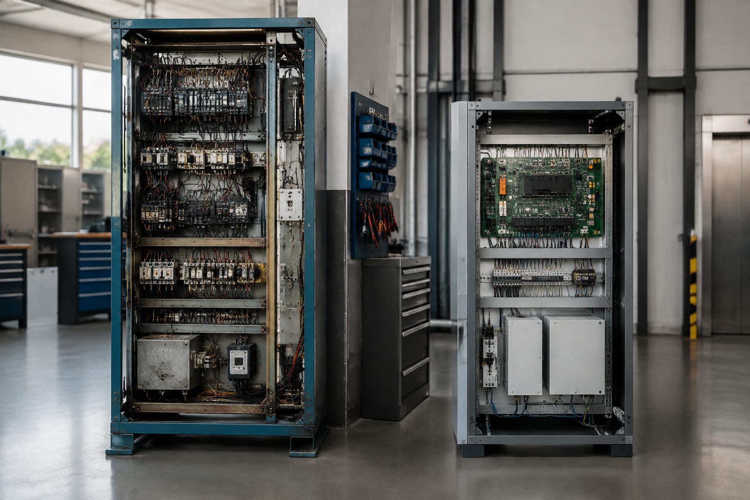
An elevator controller is the system that interprets calls, monitors the lift’s condition and commands the motor, doors and safety-related functions. The right controller is therefore not simply one with the same number of floors or a matching cabinet size. It must suit the lift’s drive type, door equipment, shaft wiring, landing signals, safety chain and required service functions.
For a replacement or modernisation, begin with a documented survey of the existing installation. Record the controller and drive details, voltages, input and output schedules, door operator interface, safety devices, travel arrangement and any building-specific functions. This avoids selecting hardware that is electrically workable but operationally incomplete.
What an elevator controller manages
The elevator controller coordinates the lift from the moment a passenger registers a landing or car call until the car stops, levels and opens its doors. It receives information from switches, sensors and communication devices, applies its control logic, then sends commands to the drive, door operator, indicators and other equipment.
Its normal responsibilities include:
- Registering and allocating car and landing calls.
- Determining direction, stopping sequence and door dwell time.
- Starting, stopping and supervising the traction machine or hydraulic power unit.
- Monitoring car position, levelling and terminal limits.
- Controlling door opening, closing, reopening and nudging functions.
- Operating car and landing indicators, gongs and displays.
- Handling independent service, fire service, emergency operation and access restrictions where fitted.
- Monitoring faults and retaining diagnostic information, where the controller supports it.
- Coordinating group operation when two or more lifts share traffic demand.
The controller does not replace every safety device. The safety chain, governor, safety gear, door interlocks and other protective equipment have distinct roles. However, the controller must interface correctly with these circuits and react predictably when a safety contact opens.
A controller’s capability should be evaluated against the actual lift, not against a generic feature list. For example, a basic two-stop goods lift may not need sophisticated group dispatching, while a commercial passenger lift may require reliable peak-traffic behaviour, destination controls, access integration or remote monitoring compatibility.
Relay-based, PLC, and integrated controls
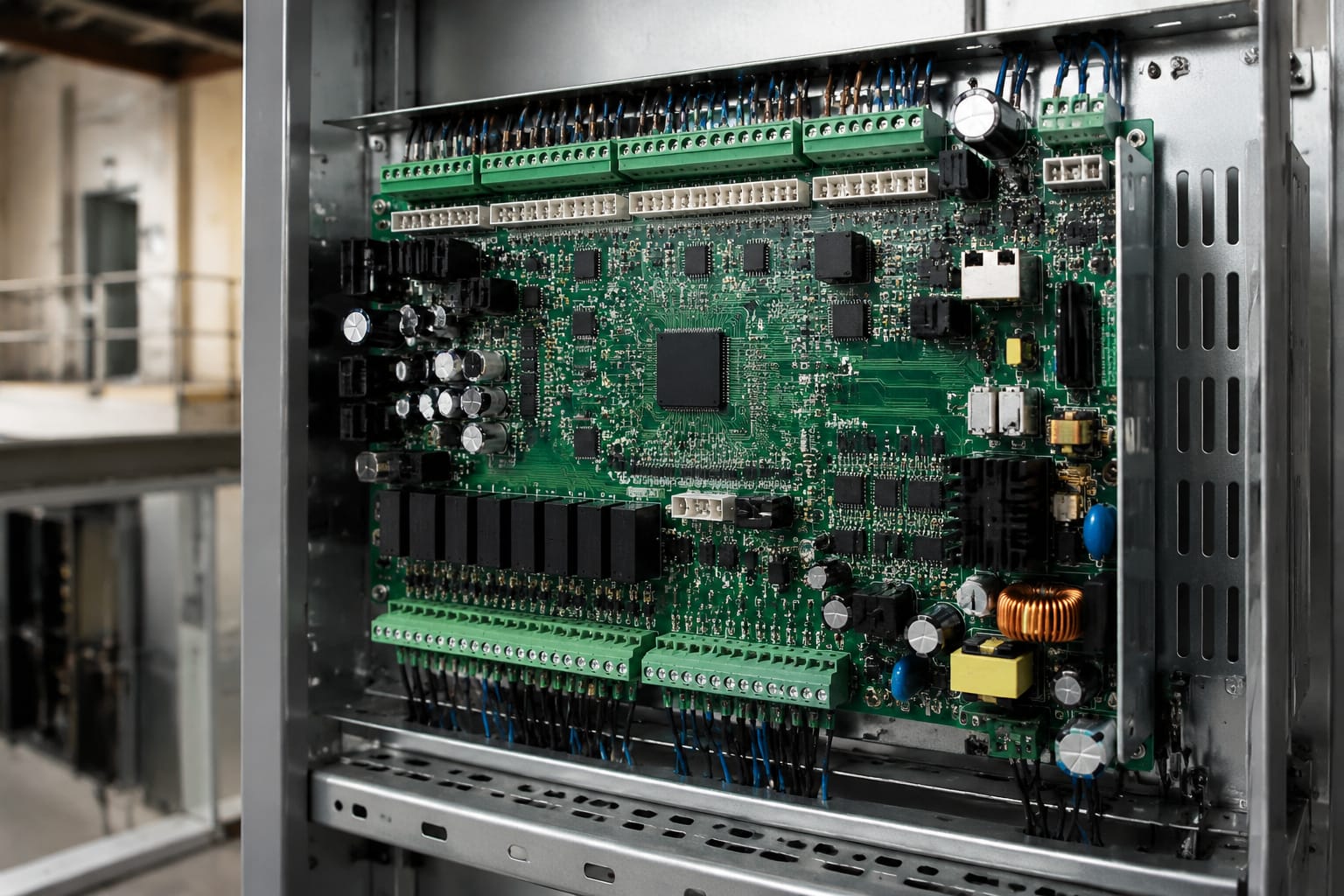
Elevator controls broadly fall into relay-based systems, programmable logic controller (PLC) arrangements and purpose-built integrated elevator controllers. The practical choice depends on the installation’s age, complexity, maintainability and the available documentation.
| Control type | How it works | Strengths | Limitations | Best suited to |
|---|---|---|---|---|
| Relay-based | Hard-wired relays, timers and contacts implement the sequence | Straightforward to trace for technicians familiar with relay logic; individual components may be replaced | Large cabinets, ageing contacts, limited diagnostics and difficult changes to operating logic | Retaining a simple, well-documented legacy lift where parts and wiring remain manageable |
| PLC-based | A general-purpose PLC runs programmed logic with separate I/O modules | Flexible for bespoke applications and interfaces; programming can be altered | Requires correct programme ownership, backups and specialist support; not every PLC arrangement is suitable for lift safety functions | Custom industrial or specialist installations with an established support model |
| Integrated elevator controller | Dedicated lift control board and software manage motion, doors, calls and diagnostics | Compact, lift-specific functions, configurable parameters and broader diagnostic capability | Compatibility depends on interfaces, firmware, licence arrangements and supplier support | Most controller replacements and modernisation projects |
Relay-based controllers
Relay controllers can remain serviceable when their wiring diagrams are accurate, the cabinet is in good condition and the lift’s use is simple. Their principal problem is cumulative maintenance: contacts wear, relay bases become unreliable, wiring modifications become hard to follow, and fault tracing can take longer as drawings drift away from the site condition.
Replacing relays one at a time can keep a lift running, but it does not necessarily reduce operational risk over the long term. When multiple functions have been modified over many years, a controlled modernisation may be easier to support than ongoing patch repairs.
Before retaining a relay controller, check whether replacement relays, timers, contactors and auxiliary contacts are genuinely obtainable, whether heat or contamination has affected the cabinet, and whether the drawings match the wiring in front of you.
PLC-based controllers
A PLC can be effective in a bespoke lift application, particularly where the lift must coordinate with conveyors, doors or industrial processes. The concern is not the PLC itself but control ownership and validation. A contractor needs a current programme, a readable backup, a record of I/O assignments and a method for making future changes safely.
Do not assume that a general-purpose PLC makes an elevator system easier to maintain. If the programme is password-protected, undocumented or held by a third party, a minor fault can become a major support issue. The safety architecture also needs proper engineering; standard control logic must not be treated as a substitute for required safety circuits.
Integrated elevator controllers
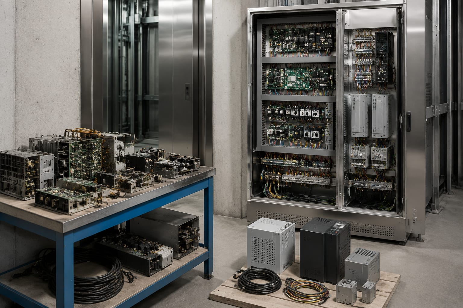
Dedicated controllers are usually the most practical route when replacing an obsolete system. They consolidate lift functions and often provide configurable floor data, door timings, fault logs and serial interfaces. Many can support a staged upgrade in which the controller, signal fixtures or door equipment are renewed separately where technically appropriate.
“Universal” should still be treated carefully. A controller may be adaptable to many lift configurations, yet still need specific interface boards, encoders, position systems, software settings or harness changes. Confirm the supported drive, door operator, landing signal protocol and safety arrangement before ordering.
Traction versus hydraulic applications
The controller must be selected for the lift’s machine-room equipment as well as its passenger-facing functions. Traction and hydraulic lifts use different motion systems, so the controller’s outputs, feedback signals and commissioning parameters differ.
Traction lift controllers
A traction controller works with a geared or gearless machine, commonly through a variable-voltage variable-frequency drive. It may need to manage run and direction commands, brake control, encoder or motor feedback, inspection operation, levelling and rescue functions.
Key checks for a traction application include:
- The drive manufacturer and model, with the exact command interface: discrete I/O, analogue reference or serial communication.
- Motor and brake supply arrangements, including contactor and brake-monitoring requirements.
- Encoder type, resolution, voltage and connection method where applicable.
- Positioning method: absolute encoder, shaft tape, magnetic sensors, switches or another system.
- Rated speed, travel, stopping distances and re-levelling requirements.
- Whether the existing drive will be retained or replaced with the controller.
A new controller may operate an existing drive using conventional contact signals, but that can sacrifice diagnostics or advanced performance available through a compatible communication interface. Conversely, replacing both controller and drive can simplify the system, although it broadens the commissioning scope.
Hydraulic lift controllers
Hydraulic applications interface with a power unit rather than a traction machine. The controller may command pump motor starting, up and down valves, levelling valves and, where fitted, soft-start or variable-speed equipment. It must also interpret pressure, levelling and valve feedback appropriate to the installation.
For hydraulic lifts, establish:
- Motor starter type and supply characteristics.
- Valve block model and coil voltages.
- Up, down and levelling valve outputs required.
- Whether the lift has direct-acting or roped hydraulic equipment.
- Existing re-levelling, low-pressure, temperature or oil-level signals.
- Emergency lowering and battery-backed functions.
- The condition and function of any hydraulic control relays that will remain.
Do not choose a hydraulic controller solely because it has the right number of stops. Valve logic, motor starting method and landing accuracy requirements are central to compatibility. Some older systems also have field modifications around re-levelling or emergency lowering that must be understood before changeover.
Door and car-top control interfaces
Door faults are among the most common causes of lift downtime, and controller replacement can expose pre-existing door interface problems. The controller must reliably command the door operator and interpret its status signals throughout normal and inspection operation.
A survey should identify whether the lift has a single automatic car door, centre-opening or telescopic doors, multiple entrances, rear doors, or manually operated landing doors. Each configuration affects the I/O count and logic.
Confirm the door operator’s:
- Supply voltage and whether it is supplied from the controller or separately.
- Open, close, common and inhibit command inputs.
- Fully open, fully closed, lock or fault feedback contacts.
- Light curtain or photocell interface.
- Nudging and door dwell requirements.
- Serial protocol, if a proprietary operator interface is fitted.
A car-top inspection station is equally important. It normally provides stop, inspection enable and up/down controls, and may include door commands or additional service functions. Its switching arrangement, voltage and safety-chain relationship must match the replacement controller’s design.
Avoid bypassing a troublesome door feedback circuit simply to complete commissioning. A persistent door input problem may indicate an incorrect interface assumption, worn contacts, a faulty harness or a door operator fault. It should be diagnosed at source.
For access-managed installations, assess the signal method before replacing boards. A dry-contact input, serial connection and networked access platform are not interchangeable. Relevant replacement components, such as an [elevator access-control motherboard](/products/5500-elevator-acess-control-board-motherboard-id-lift-parts/), should be matched to the access system’s electrical and communication requirements rather than selected by appearance.
Inputs, outputs, and safety circuits
A controller is only as compatible as its I/O arrangement. Inputs carry information into the controller; outputs command external devices. Both the number and electrical characteristics matter.
Typical inputs include car and landing buttons, door contacts, limit switches, safety-chain status, position sensors, overload signals, inspection controls and drive status. Typical outputs include lamp indications, door commands, drive run and direction commands, brake controls, gongs, displays and auxiliary relays.
Map every existing connection
Build an I/O schedule from the current controller drawings and verify it physically. The schedule should state:
- Device name and location.
- Existing terminal number and wire identification.
- Input or output type.
- Normal state: normally open or normally closed.
- Voltage, current and AC/DC requirements.
- Function during normal service, inspection and emergency operation.
- Whether the device is retained, replaced or removed.
Counting conductors is not enough. A low-voltage monitored input, a 24 V DC lamp output and a 230 V AC relay coil are not directly interchangeable. Where an interface relay, opto-isolator, fuse or separate power supply is needed, include it in the design and drawings.
Treat safety circuits as a design constraint
Safety circuits require disciplined handling. The replacement controller must accommodate the existing safety architecture and the installation’s applicable requirements. A project may require devices such as door interlocks, final limits, governor contacts, pit and car-top stops, buffers, safety gear contacts, inspection switches and emergency terminal devices to be connected in defined arrangements.
The correct approach is to review the wiring diagram, equipment manuals and the relevant project requirements with a competent lift professional. Never bridge, permanently link out or reclassify a safety contact to overcome an incompatible controller input.
Also check the distinction between monitored safety inputs and conventional series safety chains. A controller designed for monitored devices may require specific resistors, modules or wiring topology. Fitting it to an unverified legacy circuit can create recurring faults or, more seriously, defeat expected supervision.
Selecting replacement controller hardware
The best replacement controller is the one that provides a clear, supportable path from the existing system to the required operating outcome. Start with a technical compatibility decision, then compare commercial considerations.
Use this selection checklist:
- Define the objective. Is the immediate need fault recovery, improved parts availability, reduced downtime, better diagnostics, new fixtures, access control or full modernisation?
- Identify the lift configuration. Record traction or hydraulic operation, rated load and speed, number of landings, entrances, collective control type and group arrangement.
- Assess the retained equipment. Decide whether the drive, door operator, fixtures, travelling cable, position system and machine wiring are suitable to keep.
- Confirm interface compatibility. Verify each required voltage, I/O type, signal protocol, encoder and feedback circuit against the proposed hardware documentation.
- Allow for growth. Include spare I/O and capacity for a future display, access control, remote monitoring or a second entrance where appropriate.
- Check maintainability. Ensure there are current wiring diagrams, parameter backups, software access and a clear source for service parts.
- Plan the physical installation. Check cabinet dimensions, heat dissipation, ingress protection, earthing, cable entry, separation of power and signal wiring, and accessibility.
- Review documentation and handover. A controller that cannot be configured, diagnosed or restored by the maintenance team is a long-term risk.
It is usually better to specify the required functional outcome than to request “a controller for a six-stop lift”. A useful enquiry package includes photographs of the existing cabinet and nameplates, machine and drive details, schematic diagrams, terminal lists, travel information, door operator model, fixture photographs and a list of special functions.
For upgrades involving credentials or restricted floors, the controller must also accommodate the selected access hardware. Kelevator supplies multi-brand lift spare parts to B2B importers, distributors, maintenance contractors and OEM buyers; its [lift access-control boards and accessories](/products/elevator-access-control-board-motherboard-lift-accessories/) are relevant only after the required interface and control method have been confirmed.
Planning a controller modernisation
Controller modernisation should be treated as an engineered change, not a cabinet swap. The existing installation often contains undocumented alterations, ageing wiring and features that occupants notice only when they disappear.
Set the scope before ordering
A sensible scope separates retained, replaced and optional equipment. It should state whether the project includes:
- Controller cabinet and harnesses.
- Drive interface or drive replacement.
- Positioning system.
- Car and landing fixtures.
- Door operator interfaces or operator replacement.
- Travelling cable repairs or additional cores.
- Emergency communication and alarm interfaces.
- Access control, monitoring or group controls.
- Power supply modifications and protective devices.
- Updated drawings, labels and commissioning records.
This also helps prevent an incomplete order. For example, a controller may support a modern door operator, but a legacy travelling cable may lack the spare cores needed for its feedback signals. The answer could be an interface solution, cable work or a different scope, depending on condition and requirements.
Keep functions live during the design phase
Before decommissioning the old controller, capture its parameters and observed operation. Note door timings, floor labels, parking floor, collective logic, fire operation, attendant or independent service, car preference, display behaviour and any building-management interfaces. Take clear photographs of terminals, relay labels and field wiring.
Where the lift has proprietary boards that must be retained temporarily, verify whether a suitable [multi-function elevator operator interface](/products/universal-elevator-multi-function-operator-monarch-step-system-elevator-parts/) is compatible with the existing equipment and the intended control architecture. Do not assume that a board described as multi-function will resolve protocol or voltage differences without a documented match.
Manage outage and rollback risk
A modernisation plan should identify isolation procedures, outage duration assumptions, rescue arrangements, work sequencing and a rollback point. Keep removed equipment and records organised until the new system has completed functional testing. If old and new assemblies must coexist during a staged project, label every temporary connection and control the change through current drawings.
Common mistakes include reusing brittle field wiring without testing it, omitting spare parts from the scope, overlooking rear-door logic, and treating display or access-control wiring as an afterthought. These issues are cheaper to resolve during survey and design than during commissioning.
Commissioning and documentation
Commissioning proves that the installed controller performs correctly with the particular lift. It is more than confirming that the car moves and doors open.
Test the full operating sequence under controlled conditions, including:
- Car and landing calls at every served floor.
- Directional collective operation and parking behaviour.
- Accurate stopping and levelling in both travel directions.
- Door opening, closing, reopening, nudging and protection devices.
- Landing door lock and door-zone behaviour.
- Car-top and pit inspection controls.
- Normal and emergency terminal functions.
- Safety-chain response and fault indication.
- Fire service, emergency return or other site-specific modes where fitted.
- Alarm, emergency communication and battery-backed functions.
- Drive faults, power interruption and restoration behaviour.
- Group, access-control and monitoring functions if included in scope.
Tests must be performed by suitably competent personnel and aligned with the project requirements and applicable local rules. The exact acceptance process depends on the lift, building and scope of works. A controller change may affect other equipment, so test the whole system rather than only the newly installed board.
Handover documentation should include final wiring diagrams, terminal schedules, controller parameters, drive settings, software or configuration backups, fault-code information, product manuals, inspection records and a clear list of replaced components. Update cabinet labels and identify unused conductors. These records shorten future fault finding and make subsequent modifications safer.
FAQ
Can an elevator controller be replaced without changing the drive?
Often, yes. A replacement controller can sometimes retain a serviceable traction drive or hydraulic power-unit equipment. Compatibility depends on the command method, feedback signals, safety functions and condition of the retained equipment. Confirm the exact drive or valve interface before committing to the scope.
Is a PLC controller better than a dedicated elevator controller?
Not automatically. A PLC can suit bespoke applications, especially where the lift interacts with industrial equipment. For conventional passenger or goods lifts, a dedicated controller is often easier to configure and support because its functions and diagnostics are designed specifically for lift operation.
How many spare inputs and outputs should a new controller have?
There is no fixed number. Provide capacity for known additions such as access control, rear entrances, displays or monitoring, plus sensible contingency for maintenance changes. The I/O schedule should drive this decision.
Can old car and landing buttons be kept?
They can sometimes be retained if their voltage, lamp load, wiring condition and signal method are compatible with the new controller. Check each fixture type, particularly illuminated buttons and serial fixtures. Retaining old fixtures may save initial cost but can limit future reliability or appearance upgrades.
What information is needed to quote or source a controller?
Provide controller and drive nameplates, wiring diagrams, photos of terminals and fixtures, the number of landings and entrances, lift type, travel arrangement, door operator details, special functions and the intended scope. Accurate information produces a more reliable compatibility assessment.
A controller replacement is most successful when the survey, I/O schedule and commissioning plan are prepared before hardware is selected. For B2B sourcing, provide the technical pack with the required controller and interface details so compatible multi-brand components can be assessed without relying on assumptions.