
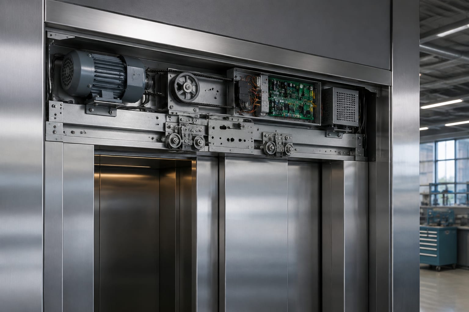
An elevator door drive is the coordinated system that opens, closes and protects the car doors. It combines a motor, controller or drive board, transmission components, door operator mechanism, feedback devices and safety sensors. A replacement succeeds only when these parts are compatible and the mechanical door system is correctly aligned.
For maintenance and modernisation work, diagnose the complete door operator before ordering a motor or board. A fault that appears electrical can be caused by drag in the hanger track, a damaged belt, incorrect limits, poor sensor alignment or a loose harness. Conversely, a mechanically sound operator will still perform poorly if its motor feedback, controller parameters or supply arrangement are wrong.
Parts of an elevator door drive
The term door drive can refer to the whole door operator assembly or, more narrowly, the motor and electronic controller that power it. In practice, the system consists of interdependent electrical and mechanical parts.
Typical components include:
- Door motor: Produces the torque to move the doors through opening and closing cycles.
- Door controller or drive board: Commands motor direction, speed, acceleration, deceleration and stopping position.
- Transmission system: Usually a belt, pulley, gear train, linkage or cable arrangement that transfers motor movement to the door panels.
- Door hanger and track: Supports the panels and allows them to travel smoothly.
- Clutch or vane: Couples the car door to the landing door at a floor.
- Feedback device: An encoder, resolver, Hall sensors, tachometer or other device that tells the controller motor position or speed.
- Open and close limits: Define or confirm end positions, depending on the operator design.
- Door protection sensor: Commonly an infrared light curtain or photocell that detects passengers or objects in the doorway.
- Door lock and proving circuits: Confirm that landing doors are locked and car doors are in the required condition before the lift can travel.
- Harnesses, connectors and power supply components: Carry power and control signals between the door equipment and lift controller.
The controller cannot compensate indefinitely for mechanical resistance. Worn rollers, contaminated tracks, bent panels and tight sill clearances increase load on the motor, raise current demand and can lead to repeated reversals or controller trips.
AC, DC and PMSM door motors
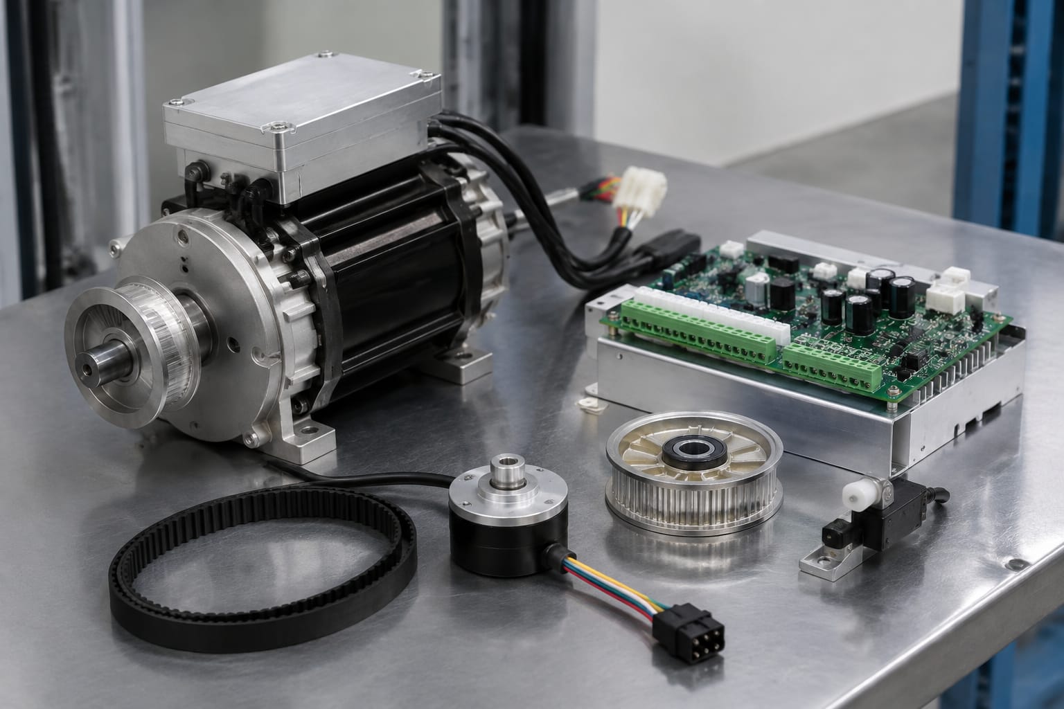
Door motors are not interchangeable simply because their mounting dimensions appear similar. Motor type affects the controller, feedback method, power supply, wiring and commissioning process.
| Motor type | Typical characteristics | Controller requirements | Key replacement checks |
|---|---|---|---|
| AC induction motor | Robust motor design; may run with basic switching or a variable-frequency drive | Correct voltage, phase arrangement and control method | Rated voltage, frequency, winding arrangement, brake provision, shaft and mounting |
| Brushed DC motor | Direct speed control and good low-speed torque; brushes and commutator are wear items | DC output compatible with rated armature voltage and current | Armature voltage, current, polarity, brush condition, tachometer or encoder compatibility |
| PMSM / brushless permanent-magnet motor | Efficient, precise control with electronic commutation; often paired with encoder or Hall feedback | Dedicated compatible drive board with correct motor data and feedback inputs | Motor constants, phases, encoder or Hall wiring, pole information where required, braking and connector pinout |
AC door motors
An AC door motor may be supplied from a control circuit or driven through an inverter. The motor must suit the controller’s output type. For example, a motor intended for variable-frequency operation cannot be assumed compatible with a simple reversing contactor circuit, and an inverter-driven arrangement needs the proper motor data and wiring.
Confirm the rated supply, frequency and phase configuration against the original documentation and the controller output. South African installations may also have differing control-transformer and mains arrangements across sites, so verify the actual operator supply rather than relying on a nominal building supply.
DC door motors
DC motors are still found in many established lift installations. Their condition is influenced by brushes, commutator wear, carbon dust, bearings and armature health. Replacing a failed DC motor with an alternative rating can damage the board or produce unsuitable closing force and speed.
A DC motor replacement needs more than a matching physical frame. Check rated armature voltage, normal and peak current, rotational direction, shaft geometry, mounting, brake arrangement and feedback interface. If the original motor includes an encoder or tachometer, that feedback must match the drive board’s expected signal type and resolution.
PMSM and brushless door motors
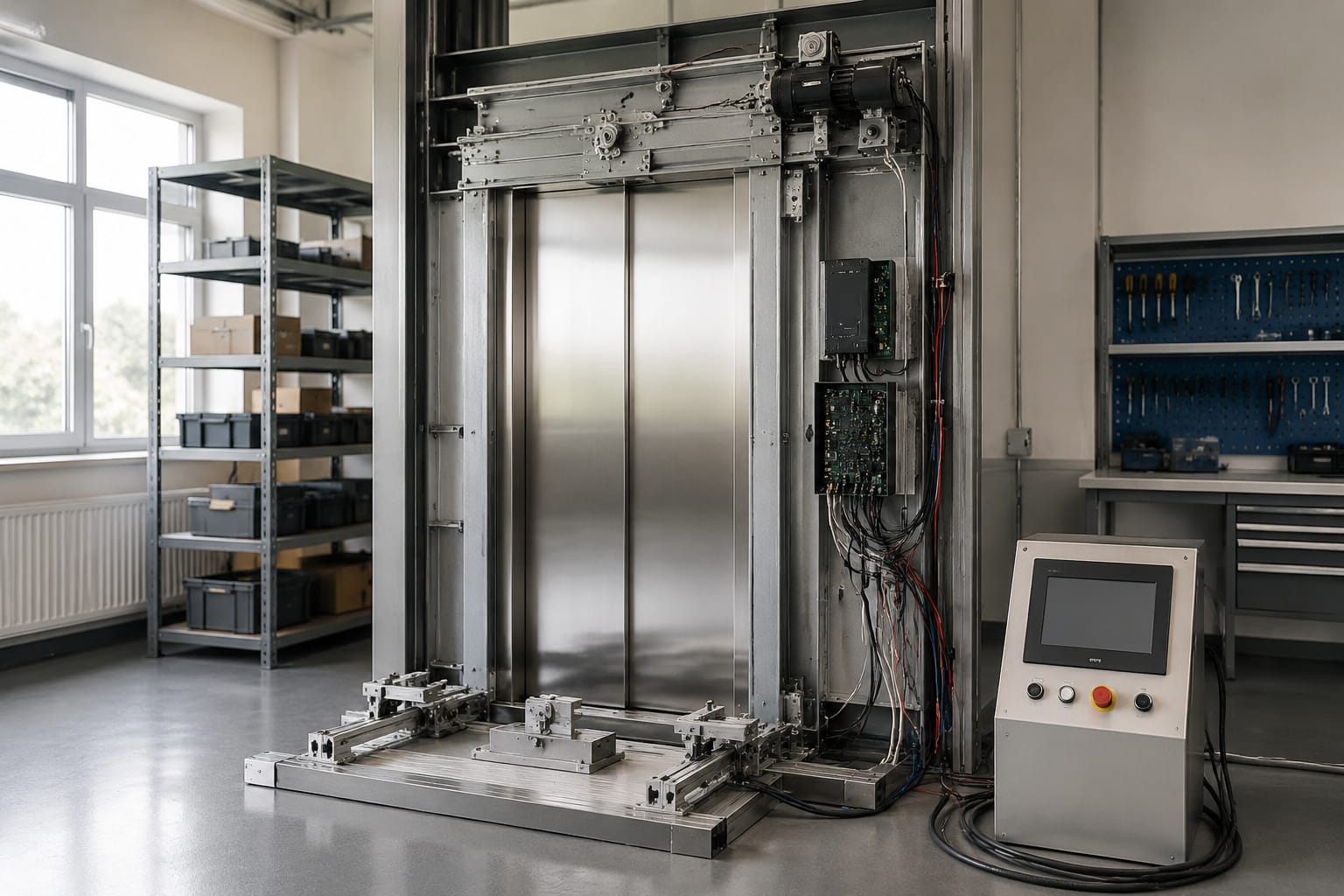
Permanent-magnet synchronous motors, including brushless designs, require a controller that can commutate the motor correctly. Phase order, motor feedback and programmed motor data matter. An incorrect phase sequence or feedback connection may cause rough movement, a failure to start, incorrect direction or a drive fault.
Do not connect an unknown PMSM motor to a controller merely to test it. Record the original motor and board identifiers, connector pinout and feedback details first. Where a complete matched replacement is available, it normally reduces compatibility risk compared with mixing unrelated motor and controller families.
Door controllers and drive boards
The door controller is the decision-making and power-control part of the operator. It receives commands such as open, close, nudge or hold-open, monitors feedback and safety inputs, and energises the motor accordingly.
Its functions commonly include:
- Controlling motor speed and direction
- Applying acceleration and deceleration ramps
- Learning or enforcing opening and closing travel
- Monitoring motor current or torque for obstruction detection
- Processing encoder, Hall sensor or limit-switch signals
- Responding to the light curtain, photocell and reopen circuit
- Reporting faults through LEDs, displays, relays or communications
- Supervising door-close confirmation required by the lift controller
The term drive board is often used for the controller PCB, but some operators use separate logic and power boards. Others integrate the board inside a dedicated door controller enclosure. Identify the actual failed component before purchasing: a power board, control board, encoder interface or damaged cable can all present as a door drive fault.
When comparing parts, review the board part number, revision, software or firmware designation where shown, connector arrangement and motor type. A similar-looking board can have different logic inputs, output ratings or parameter defaults.
For component-level replacements, relevant options include [Hitachi door motor drive boards](/products/door-motor-drive-board-hitachi-elevator-parts-lift-accessories/) and [HGP Hitachi door motor control boards](/products/door-motor-drive-control-board-hgp-hitachi-elevator-parts-lift-accessories/). The product reference should still be checked against the operator’s existing board label and application details.
Feedback, limits and safety sensors
Feedback and safety inputs allow the door drive to control movement accurately and react safely to obstructions. A motor can be healthy while a faulty feedback device prevents normal operation.
Motor feedback
Common feedback methods are:
- Incremental encoders, which provide pulses used to calculate speed and position
- Absolute encoders, which report a specific shaft position
- Hall sensors, often used by brushless motors for rotor position
- Tachometers, which provide speed feedback on some DC systems
- Current sensing, which helps the controller estimate load or obstruction
Encoder faults may cause hunting, jerky travel, overshoot, unexpected reversal or a controller fault soon after movement begins. Check connector seating, cable damage, contamination, supply voltage to the device and signal wiring before condemning the motor.
Limits and door-position confirmation
Some door operators use mechanical or magnetic limit switches to stop or confirm travel. Others use encoder counts and software-learned positions. In either case, incorrect open and close positions can leave panels short of their intended travel, overrun the mechanism or prevent reliable door-lock operation.
Never bypass a limit, door-lock circuit or position input to keep a lift running. A bypass may conceal the actual fault and can defeat a safety function.
Light curtains and photocells
A light curtain or photocell normally reopens the doors when its protected field is interrupted. Persistent reopening can result from a blocked sensor path, dirty lenses, damaged emitter or receiver wiring, poor alignment, incorrect sensitivity settings or a failed controller input.
The sensor should be tested through its normal operating range, including low and high beams where applicable. Cleaning alone is not a complete diagnosis; confirm that the controller receives the expected signal and that the doors respond correctly.
Common door-drive fault symptoms
Symptoms are useful starting points, not conclusive diagnoses. The same symptom can have mechanical, electrical and configuration causes.
| Symptom | Likely areas to inspect | Avoid assuming |
|---|---|---|
| Doors do not move | Supply, fuses, controller status, command inputs, motor circuit, seized mechanism | That the motor has failed |
| Doors move slowly | Track and rollers, belt tension, panel drag, motor wear, controller speed setting | That increasing speed parameters is the solution |
| Doors reopen repeatedly | Light curtain, photocell, close input, door edge, resistance detection, sill obstruction | That the sensor is necessarily defective |
| Doors slam or stop harshly | Deceleration settings, limit positions, belt or linkage condition, feedback, panel alignment | That the controller needs replacement |
| Doors stop part-way | Encoder or Hall feedback, current limit, mechanical binding, harnesses, travel settings | That the door panels are correctly aligned |
| Board trips or shows a motor fault | Motor winding condition, insulation, cable damage, connector pinout, output stage, mechanical load | That a new board will solve the underlying cause |
| Correct movement in one direction only | Direction command, output stage, relay or contactor, phase or polarity, limit logic | That the motor is mechanically one-directional |
A disciplined fault process starts with safe isolation where required, a visual inspection and a check of the operator’s manual movement. Inspect rollers, tracks, belt or linkage, fasteners, door panels, sill and clutch before making parameter changes. Then review controller indicators or fault codes, inputs, supply voltages and feedback signals using appropriate test equipment.
Match motor and controller specifications
The best replacement choice is a matched original-equipment part or a documented equivalent that is compatible with the whole door operator. Matching only the motor’s voltage or the board’s connector shape is inadequate.
Use this checklist before ordering a motor, board or complete door drive:
- Record the lift and door operator manufacturer, model and serial information.
- Photograph the existing motor, controller labels, connectors and wiring before removal.
- Confirm the original part number and board revision.
- Identify the motor technology: AC, brushed DC, PMSM or brushless DC.
- Confirm rated voltage, current, frequency and phase arrangement where applicable.
- Check motor mounting centres, shaft diameter and length, pulley or gear attachment, and rotational direction.
- Identify the feedback system, connector type, signal format and cable length.
- Check whether the motor includes a brake and verify brake voltage and control arrangement.
- Compare controller inputs and outputs, including safety sensor, limits, door-close proof and lift-controller interface.
- Establish whether parameter transfer, software configuration or a learn cycle is required.
- Confirm that the replacement suits the operator, not just the lift brand.
Where an exact board reference is unavailable, provide a clear label photograph and the motor details to the sourcing team. Kelevator supplies multi-brand elevator spare parts for B2B importers, distributors, maintenance contractors and OEM buyers; accurate identification details help a buyer evaluate the correct part without relying on appearance alone.
A [door motor board for lift applications](/products/door-motor-board-lift-parts-elevator-accessories/) may be relevant to a board replacement, but compatibility must be verified against the installed operator’s requirements.
Parameter setup and mechanical alignment
Replacement hardware usually requires setup. Installing a compatible motor or board without configuring it can result in unsafe or unreliable operation.
Set the mechanics first
Before adjusting software parameters, make sure the door panels travel freely with the drive disengaged or according to the operator manufacturer’s approved method. Address mechanical defects first:
- Clean the track and sill of debris.
- Inspect hanger rollers and guides for wear, damage and correct adjustment.
- Check panel alignment and clearances.
- Inspect belt, cable, pulley, linkage or gear components for wear and correct tension.
- Tighten appropriate fasteners to the equipment manufacturer’s requirements.
- Confirm that the clutch or vane engages landing doors correctly.
- Check that door locks and associated mechanisms operate without excessive force.
Do not use higher torque, current limits or closing force settings to overcome a binding door. That can mask the issue while increasing wear and reducing the effectiveness of obstruction detection.
Configure controller parameters
Parameter names differ between manufacturers, but setup commonly includes:
- Restoring the correct motor type and electrical data.
- Confirming rotation direction before allowing full-speed travel.
- Setting or learning fully open and fully closed travel positions.
- Adjusting opening and closing speed within the operator’s approved range.
- Setting acceleration and deceleration to achieve smooth movement.
- Configuring obstruction detection, reopening behaviour and nudging as specified for the equipment.
- Checking light curtain or photocell input logic.
- Saving parameters and recording final values for future maintenance.
Use the operator manual and controller documentation for every setting. Values cannot be transferred blindly between different door operators, panel weights or site conditions. A parameter set that works on one lift can cause poor movement or faults on another.
Common setup mistakes
Frequent causes of return visits include reversing motor direction through incorrect wiring, setting limits before alignment, leaving encoder cables strained, changing multiple parameters at once, and failing to record the original configuration. Make controlled changes, test the result after each change and keep a commissioning record.
Commissioning the door system
Commissioning confirms that the complete door system works together, rather than simply proving that the motor turns. It should be performed by competent personnel following the applicable equipment documentation and site safety procedures.
A practical commissioning sequence is:
- Verify that the correct parts, wiring connections and earthing arrangements are in place.
- Inspect the mechanical installation, guards, belt or linkage, panel movement and fasteners.
- Power up and check the controller’s normal status indications before commanding movement.
- Confirm motor direction at controlled speed.
- Learn or set open and close positions as required by the door operator.
- Run repeated open-close cycles and observe smoothness, noise, stopping position and panel alignment.
- Test light curtain or photocell operation across the protected opening.
- Test obstruction detection and reopening behaviour using the manufacturer-approved method.
- Confirm door-close and landing-lock proving signals required before lift travel.
- Review fault history, document installed part references and record final parameter values.
The lift should not be returned to normal service until the door system performs correctly through its full sequence and all relevant protective functions have been checked. Where controller diagnostics identify a recurring fault, investigate the wiring and mechanical load rather than repeatedly resetting the fault.
FAQ
Can a different motor be used with the existing door controller?
Only where its electrical ratings, feedback method, mechanical fit and control requirements are confirmed compatible. A motor that physically fits may still overload the controller or provide unusable feedback.
Is it better to replace the motor or the drive board?
Replace the failed component only after diagnosis. A motor fault can damage a drive board, and a failed board can make a healthy motor appear faulty. Check motor windings, insulation, cables, feedback and mechanical load before deciding.
Why do elevator doors reverse when nothing is in the opening?
Check the light curtain or photocell first, then inspect for panel drag, a contaminated sill, incorrect closing force or current sensing, feedback errors and close-command wiring. Reversal is a protective response, so its cause should be identified rather than disabled.
Do new door controllers need programming?
Often, yes. Some units require travel learning, motor configuration, speed settings or input logic setup. Confirm the commissioning requirements before removing the existing board so original settings can be recorded.
For a planned replacement, compile the existing motor and controller labels, photographs of connectors, fault information and door operator details before sourcing parts. This makes it possible to assess the door drive as a matched system and plan the required setup work.