
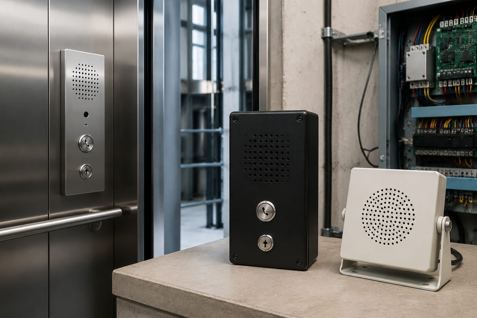
Elevator intercom systems provide a dedicated voice path between a trapped passenger and people who can arrange assistance. A dependable installation is more than a handset in the car: it combines the car station, an answering point, suitable wiring, a stable power source and a tested emergency-call procedure.
For maintenance and modernisation work, the right replacement depends on the existing controller and communication layout. Identify every station, cable route, interface type and backup-power requirement before selecting parts. A unit that physically fits the car operating panel may still be unsuitable if it uses the wrong voltage, wiring arrangement or call protocol.
What an elevator intercom system does
An elevator intercom system enables two-way communication when normal lift operation is unavailable or when a passenger needs assistance. In a basic arrangement, pressing the alarm or call button in the car creates a call to a nominated answering point. That point may be a machine-room handset, security desk, duty room, monitoring centre or another designated location.
The system should make it clear that a call has been placed and, where applicable, that it has been answered. Its function is communication, not passenger release or fault correction. The person receiving the call still needs a defined procedure for confirming the site, contacting the maintenance provider and arranging attendance.
Common functions include:
- Calling from the car to a local handset or remote attendant.
- Voice communication between the car and machine room during maintenance.
- Calling one or more designated stations from the car.
- Indication of a call, answered call or system fault, depending on the equipment.
- Continued emergency communication during a mains interruption where backup power is specified.
An intercom should not be confused with a standard building telephone extension, an auto-dialler, a GSM emergency phone or a lift-monitoring gateway. Some products combine functions, but their connection method, power supply and failure modes can differ substantially. Establish what the existing equipment actually does before treating one as a substitute for another.
Two-way and multi-station configurations
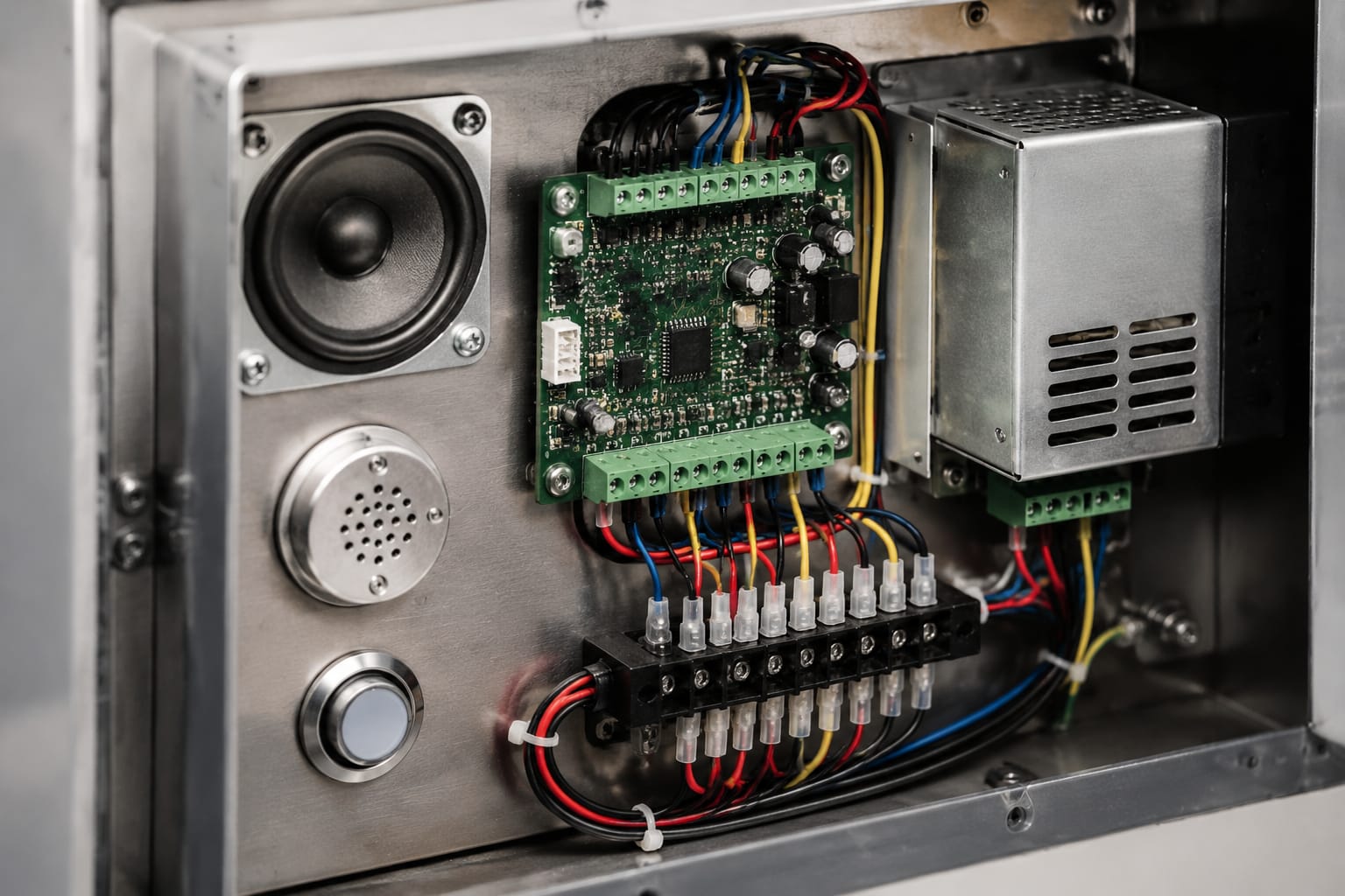
The simplest decision is whether the lift needs communication with one answering location or several. The number of stations is only part of the question; the call-routing behaviour matters just as much.
| Configuration | Typical layout | Best suited to | Key checks |
|---|---|---|---|
| Two-way intercom | Car station to one machine-room, duty-room or security station | Small sites with a reliably staffed response point | Cable pair count, call indication and whether the recipient is continuously available |
| Multi-station intercom | Car station calls or communicates with multiple local stations | Buildings where reception, security and a duty room may share responsibility | Call priority, simultaneous ringing, answering sequence and station addressing |
| Car-to-machine-room communication | Car station linked directly to machinery-space equipment | Maintenance communication and local emergency response | Distance, cable protection and access to the answering station |
| Remote communication solution | Car unit communicates through a remote communications interface | Sites where the response point is not near the lift | Network or telephone service dependency, site signal conditions and backup operation |
A two-way configuration is easier to trace and often easier to maintain. Its weakness is operational: it only works as intended while the single answer point is reachable. A machine-room handset can be appropriate for technician communication, but it may not be a suitable sole emergency answering point if the room is unattended.
Multi-station arrangements improve the chance that someone answers, but introduce configuration risks. Stations may need individual addresses, correct polarity or programme settings. A replacement must preserve the intended ringing order and prevent a local handset from unintentionally blocking a call to the duty station.
Before selecting a multi-station system, document:
- Which station receives the first call.
- Whether all stations ring together or in sequence.
- Whether a call can be transferred or answered by more than one station.
- What happens when no station answers.
- How the car user knows the call is active and answered.
- Who is responsible for checking the system outside normal operating hours.
Car, machine-room and duty-room stations
Each intercom station has a specific role. Treating them as interchangeable is a common cause of unsuitable replacements.
Car stations
The car station is the passenger-facing point, usually installed behind or within the car operating panel. It may contain a speaker, microphone, call button, status indicator, handset connection or a combination of these. It must suit the panel cut-out, mounting depth, acoustic environment and the controller or intercom system it connects to.
Confirm the following before replacing a car unit:
- Panel aperture, fixing centres and available depth behind the panel.
- Microphone and speaker orientation; poor positioning can cause low volume or feedback.
- Button contacts and whether the alarm button is integral to the unit.
- Required supply voltage and current.
- Number and type of terminals or connectors.
- Whether the unit is analogue, digitally addressed or proprietary.
- Any visual acknowledgement required by the installation specification.
For a direct component comparison, a supplier listing may identify the intended product family, but compatibility still needs confirmation from the part number, wiring diagram and system architecture. Kelevator supplies multi-brand spare parts for B2B buyers; its elevator intercom phone components are relevant only after those details have been matched to the existing installation.
Machine-room stations
A machine-room station supports local communication between the car and maintenance personnel. It may be a wall-mounted handset, desk station or unit installed near the controller. Its value lies in allowing work to be coordinated without relying on shouted communication through the hoistway.
The station should be accessible without obstructing controller access. Route cables away from power conductors where required by the product documentation and site practice. Label the station and its associated lift clearly, especially where several lifts share a machinery space.
Do not assume an older machine-room intercom can be retained with a new car station. Older systems commonly depend on a matched master station or dedicated supply. Check the manufacturer wiring documentation and verify operation before and after any replacement.
Duty-room and security stations
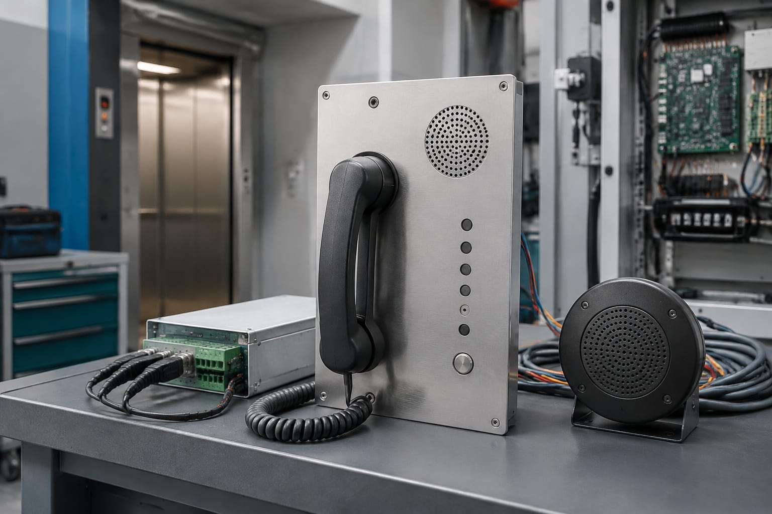
A duty-room station is intended for staff who respond to calls, such as security, concierge or facilities personnel. The essential issue is not its location but the response process. Staff need to know which lift is calling, how to speak to the passenger and what escalation action to take.
Where several lifts terminate at one desk, clear lift identification is important. A generic ringing handset can leave staff unable to establish the source of the call quickly. Consider whether the station needs separate call indicators, a display, identifiers or a documented call sequence.
A local station also depends on the building’s staffing model. If the desk is regularly unattended, a different primary or secondary call path may be necessary. Equipment selection cannot compensate for an unanswered number or an unclear emergency process.
Power supplies and backup power
The intercom power supply determines whether the system remains operational and how reliably it communicates. Some systems use a dedicated intercom supply, while others are powered from the lift controller, a communications device or a combination of sources. The correct arrangement is specific to the equipment.
A dedicated supply may provide regulated voltage and, in some designs, battery charging or changeover capability. A dedicated Otis intercom power supply illustrates why brand, model and electrical matching matter: do not replace a dedicated unit with a generic supply solely because the nominal output appears similar.
For any supply replacement, verify:
- Input voltage, frequency and protective arrangement.
- DC output voltage, polarity, current capacity and permitted load.
- Battery type, voltage, capacity range and charging requirements, where fitted.
- Terminals for car, machine-room, remote station and alarm interfaces.
- Whether the system shares a common reference with the controller.
- Fuse ratings and the cause of any blown fuse before replacement.
- Enclosure, mounting, ventilation and access requirements.
Backup power needs special attention. A lift may lose mains supply at the same time a passenger requires help. The emergency communication path must therefore be assessed during loss of normal supply, not merely while the lift is operating normally.
Battery-backed systems need periodic inspection. A battery can show an acceptable terminal voltage with no load yet fail when the intercom places a call. Check date markings where provided, terminals for corrosion, charger operation and the system’s actual operation on backup power. Replace batteries only with a type and rating approved for the equipment.
Wiring and communication interfaces
Intercom wiring is often the deciding factor in a replacement project. Before disconnecting equipment, record terminal designations, conductor colours, cable routes, screen connections and jumper settings. Photographs are useful, but they do not replace a legible terminal schedule.
Common communication methods include:
- Analogue two-wire or multi-wire voice circuits.
- Separate pairs for speech, call signal, door zone or status indication.
- Proprietary multi-core systems with dedicated master and slave stations.
- Controller-integrated digital interfaces.
- Telephone, network or mobile communications interfaces used by remote emergency equipment.
Never infer a wiring method from the number of cores alone. A four-core cable may serve separate speaker and microphone circuits, call functions or a proprietary arrangement. Conversely, a modern system may carry several functions on fewer conductors but require an incompatible bus interface.
Cable routing and interference
Poor routing can degrade audio even where every terminal is correct. Long parallel runs near variable-speed drives, motor cables, contactors or other high-current circuits can introduce hum, buzz or intermittent noise. Follow the equipment instructions for segregation, screening and earthing. Do not connect a cable screen at both ends unless the system design calls for it; incorrect screen termination can create unwanted current paths.
Travelling cable condition is particularly important. Repeated flexing can cause intermittent conductors that pass a static continuity check but fail when the car moves. Test while observing cable movement where it is safe to do so, and inspect for damage at termination points.
Interface compatibility
A replacement intercom must match more than the wiring. Check whether it needs:
- A dry contact, voltage input or serial command from the lift controller.
- A normally open or normally closed alarm circuit.
- A particular call-button resistance, supervised input or end-of-line component.
- A line-powered, low-voltage or battery-supported station.
- A matched master station, interface board or programming tool.
- An external communications service and its site-specific connection requirements.
Changing from a local wired intercom to a telephone- or mobile-based emergency solution can reduce dependency on a duty-room handset, but it also adds service, signal, network and configuration dependencies. Treat this as a system redesign, not a like-for-like handset swap.
Audio and call-quality problems
Most intercom faults fall into a small number of categories: no call, one-way audio, poor audio, intermittent communication or failure during a power outage. Efficient diagnosis starts by determining whether the fault is at the car, receiving station, power supply, wiring or configuration.
| Symptom | Likely areas to investigate | Practical first checks |
|---|---|---|
| No call indication | Call button, input wiring, supply, address or programming | Verify supply, button operation, terminals and station configuration |
| Car can hear but cannot be heard | Car microphone, microphone wiring or car electronics | Check microphone connection, contamination, cable continuity and known-good station behaviour |
| Receiving station can hear but car cannot | Speaker, speaker wiring or amplifier output | Check speaker circuit, volume setting and output connection |
| Hum, buzz or distortion | Cable routing, screen connection, power supply or grounding | Compare with a temporary test lead where appropriate; inspect routing and supply ripple |
| Feedback or echo | Microphone/speaker placement, volume setting or damaged acoustic parts | Check panel mounting, seals, grille blockage and level settings |
| Works on mains but fails on backup | Battery, charger, changeover circuit or inadequate battery capacity | Test under the specified backup condition and inspect battery health |
| Intermittent calls when the car moves | Travelling cable, loose terminals or cable strain | Inspect and test flexing sections, car-top terminations and controller connections |
Do not adjust volume controls first when the fault is distorted or intermittent. Excess gain can create feedback and mask a wiring or hardware issue. Start with supply voltage under load, terminal integrity and the exact direction of the failed audio path.
Physical issues are frequently overlooked. A blocked microphone grille, damaged speaker cone, loose car operating panel, water ingress or paint contamination can significantly affect speech quality. Replace or repair the affected component rather than compensating with excessive volume settings.
Replacement and upgrade planning
The lowest-risk replacement is a documented compatible part installed and tested against the existing system. An upgrade is justified when the current arrangement cannot provide an appropriate answer path, cannot operate on required backup power, has recurring faults or relies on obsolete components that cannot be maintained reliably.
Start with a site survey and component record. Capture the lift make and controller model, existing intercom part numbers, station count, supply details, terminal schedule, cable type, physical dimensions and fault history. For remote systems, capture the communication path and any service account or programming information that the responsible party must retain.
A practical compatibility checklist
Before ordering or fitting an intercom component, confirm:
- It is intended for the specific lift or intercom product family, or is demonstrably compatible.
- The function matches: car station, master station, duty-room station, interface, power supply or handset.
- Supply voltage, polarity and current requirements match.
- The terminal layout and communications method are compatible.
- The physical fit suits the panel, enclosure or mounting rail.
- Existing cable cores and cable condition are adequate.
- Required visual and audible call indications are retained.
- Backup-power operation is compatible with the installed battery and charger arrangement.
- The response point and call-routing configuration remain operational.
- The work aligns with the applicable site requirements and South African safety obligations.
Common mistakes include ordering by appearance alone, replacing only the handset when the power supply is defective, joining incompatible systems through improvised adapters, and leaving no updated wiring record. Another frequent error is failing to test the communication path after a controller change or electrical work in the machine room.
Where a complete matched system is required, component families matter. For example, a Hitachi elevator intercom system component should be assessed against the relevant system documentation and installed configuration, rather than assumed to work across all brands or controller generations.
For modernisation projects, decide early whether to retain local stations, add a monitored answer point, or move to a remote communications solution. Each choice affects wiring, power resilience, ongoing administration and the emergency response procedure. The best option is the one that can be maintained and answered reliably throughout the building’s operating pattern.
Functional and emergency-call testing
Testing must prove both speech quality and the complete emergency communication process. A successful lamp test or dial tone is not enough. Test after installation, after controller or communications changes, and as part of the maintenance regime required for the site.
A useful functional test covers:
- Place a call from the car and confirm that the correct station or service receives it.
- Confirm clear two-way speech at normal speaking volume.
- Check call, answered and fault indications where the system provides them.
- Test each car and each designated answering station in a multi-station layout.
- Confirm lift identification at the receiving point.
- Check that the recipient can follow the documented response procedure.
- Test communication with normal mains supply removed only where it can be done safely and in accordance with the equipment instructions.
- Record the result, defects found, corrective work and the next required test.
Avoid testing in a way that creates an unmanaged passenger risk. Coordinate planned testing with the responsible site contact, ensure the lift’s operating state is understood, and do not simulate a trapped-passenger event without suitable controls.
Keep the test record with the lift maintenance documentation. It should identify the lift, date, technician or responsible person, stations tested, backup-power result, audio issues and actions taken. Good records make recurring faults easier to isolate and give the next maintenance team an accurate starting point.
A reliable elevator intercom system is selected as a complete communication path, not as an isolated handset. For replacements, use the existing part number, wiring information and power details to compare compatible components; for upgrades, define the answer point and emergency procedure before choosing the technology.
Related product references
For practical catalog examples related to this topic, review [Intercom System Phone Hitachi elevator parts lift accessories](/products/intercom-system-phone-hitachi-elevator-parts-lift-accessories/), [Intercom Dedicated Power Supply OTIS elevator parts lift accessories](/products/intercom-dedicated-power-supply-otis-elevator-parts-lift-accessories/), and [Intercom Phone elevator parts lift accessories](/products/intercom-phone-elevator-parts-lift-accessories/). Confirm the exact model, dimensions, ratings, and connectors before ordering.