
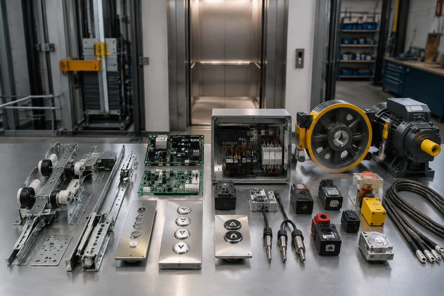
An elevator parts catalog groups replacement components by function, such as doors, controls, traction, safety and communication. To find the correct part, buyers need more than a component name: the lift manufacturer, model or controller family, part number, electrical rating, connector layout, dimensions and clear photographs may all be required.
The 12 component groups below cover many common maintenance and modernisation requirements. Because visually similar parts are not necessarily interchangeable, every selection should be checked against the installed equipment and the lift's technical documentation before ordering or fitting.
How an elevator parts catalog is organised
Most catalogues are organised around lift subsystems rather than listing every component in one long sequence. This allows a maintenance contractor or sourcing team to move from the reported fault to the relevant assembly and then to the individual replacement part.
A practical catalogue structure usually includes:
| Component group | Typical catalog entries | Important matching details |
|---|---|---|
| 1. Door operators and motors | Door motors, operator assemblies, belts and pulleys | Motor rating, opening type, mounting and drive arrangement |
| 2. Door control boards | Door motor boards and inverter boards | Part number, software version, connectors and supply voltage |
| 3. Door mechanical and safety parts | Rollers, guides, interlocks and safety edges | Door type, dimensions, handing and contact configuration |
| 4. Push buttons | Call buttons, alarm buttons and key switches | Cut-out size, voltage, illumination and contact type |
| 5. Operating panels | Car and landing panels, faceplates and keypads | Layout, dimensions, communication protocol and finish |
| 6. Position displays | LED, LCD and dot-matrix indicators | Input protocol, display format, voltage and connector pinout |
| 7. Controllers and circuit boards | Main boards, interface boards and drive boards | Board code, revision, firmware and controller family |
| 8. Relays and contactors | Relay boards, plug-in relays and contactors | Coil voltage, contact rating, pin layout and duty |
| 9. Traction components | Sheaves, ropes, belts and bearings | Dimensions, groove profile, material and load requirements |
| 10. Encoders and motion feedback | Rotary encoders, magnetic encoders and couplings | Resolution, shaft size, output type and supply voltage |
| 11. Sensors and safety devices | Levelling sensors, limit switches, governors and buffers | Operating method, ratings, mounting and approved application |
| 12. Communication and emergency parts | Intercoms, alarm units, batteries and emergency lights | System compatibility, power requirements and interface type |
Catalogues may also be arranged by manufacturer, lift model, controller series or original part number. Manufacturer-based browsing can narrow the search, but the name on the lift car is not always enough. A lift may have been modernised with a controller, door operator or drive from a different supplier.
Treat the catalogue as an identification tool, not proof of interchangeability. The final check should use data from the actual component and installation.
Door-system components
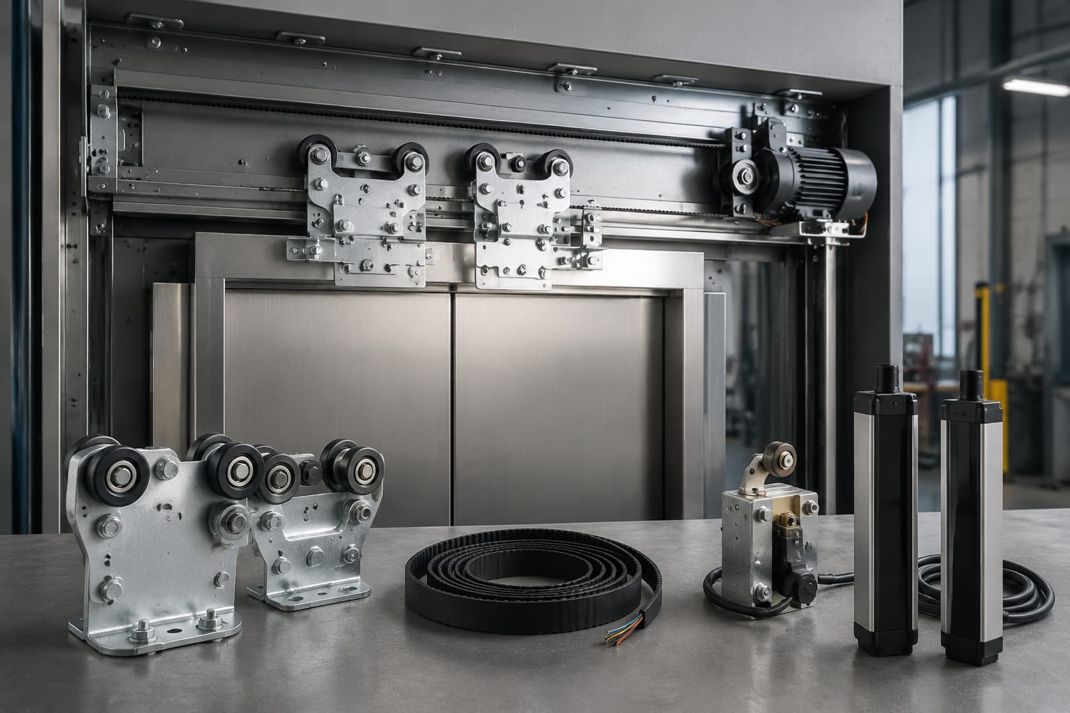
Lift doors account for several distinct mechanical, electrical and safety components. When a door fault occurs, identifying the failed subsystem first prevents unnecessary replacement of the complete operator.
1. Door operators and motors
The door operator controls opening, closing, speed and torque. A catalog entry may refer to a complete operator, a motor, an inverter, a belt or a pulley. Buyers should establish whether the lift has centre-opening, side-opening or another door configuration.
For a door motor, confirm:
- Manufacturer and complete model reference
- Rated voltage, current, power and frequency
- AC, DC, brushless or other motor type
- Shaft diameter, length and orientation
- Mounting-hole positions
- Pulley or coupling arrangement
- Connector type and pinout
- Feedback device, where fitted
Do not select a replacement solely by motor power. Two motors with similar ratings can have different feedback systems, mechanical interfaces or control requirements.
2. Door control boards
A door motor board manages motor commands and may monitor door position, speed or obstruction inputs. The board must communicate correctly with both the operator and the lift controller.
Match the full printed circuit board number, including suffixes and revision marks. Also record the controller or door-operator model, connector positions and any firmware or parameter label. A useful reference is this example of a [Hitachi elevator door motor board](/products/door-motor-board-hitachi-elevator-parts-lift-accessories/), which shows the type of component buyers may encounter in the door-control category.
A board that looks identical may still have different firmware, component values or input logic. Never move jumpers, memory devices or configuration chips without following the relevant technical procedure.
3. Door mechanical and safety parts
This category includes:
- Hanger rollers and counter-rollers
- Door shoes and guide gibs
- Belts, cables, springs and pulleys
- Car-door and landing-door interlocks
- Door contacts
- Light curtains and safety edges
Dimensions are particularly important for mechanical parts. Record roller diameter, width, bearing size and bore; belt profile and length; or interlock mounting centres and contact arrangement, as applicable.
Door interlocks and protective devices are safety-related. Substituting a mechanically convenient part without verifying its intended application, electrical contacts and operating geometry can compromise safe operation. These parts should be selected and installed by appropriately qualified lift personnel.
Buttons, panels, and displays
Fixtures are visible to passengers, but their compatibility depends on the electrical and communication system behind the faceplate.
4. Push buttons and key switches
A replacement call button must fit the panel and provide the correct electrical function. Check the panel cut-out, button diameter or body dimensions, fixing method and terminal arrangement.
Also confirm:
- Illumination voltage and colour
- Momentary or maintained operation
- Normally open or normally closed contacts
- Tactile, mechanical or touch-sensitive design
- Symbol, legend or braille requirements
- Indoor, exposed or vandal-resistant application
For key switches, the key-removal position and contact sequence matter. Similar-looking switches may perform different control functions.
5. Car and landing operating panels
A car operating panel generally contains floor buttons, door controls, alarm controls, indicators and sometimes communication equipment. A landing operating panel normally contains one or more call buttons and may include a direction or position display.
Complete panels require more information than individual buttons. Supply the faceplate dimensions, fixing details, floor arrangement, cut-outs, engraving or markings, communication interface and finish. For an existing panel, photographs of the front and rear help establish whether the fixture uses conventional wiring, serial communication or a dedicated interface board.
Where only the faceplate is damaged, replacing the entire panel may be unnecessary. Conversely, fitting new buttons into a heavily modified or corroded panel can create alignment and durability problems. Compare the condition, compatibility and labour implications before choosing the repair scope.
6. Position and direction displays
Position indicators can use discrete wiring, binary inputs, serial communication or a manufacturer-specific protocol. Matching the screen size and appearance is therefore not sufficient.
Capture the display board number, supply voltage, connector pinout, number of floors, character format and communication details. Confirm whether the unit displays floor position only or also direction arrows, messages and audible signals.
Controllers, boards, and relays
Electronic control parts require some of the most careful identification in an elevator parts catalog. Board revisions and software differences can affect compatibility even within the same product family.
7. Controllers and circuit boards
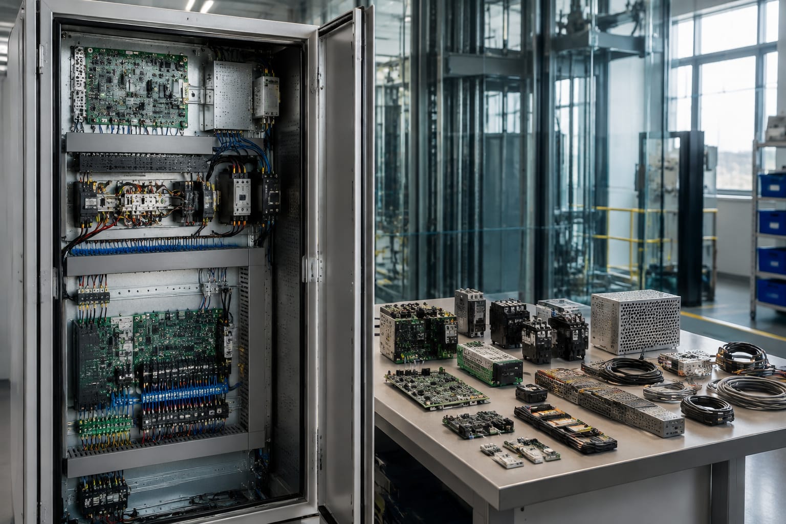
This group can include main controller boards, input/output boards, drive interfaces, communication boards, power-supply boards and car-top control boards.
For accurate sourcing, provide:
- Full board number and revision
- Lift or controller manufacturer
- Controller and drive model
- Firmware or software label, if shown
- All connector labels and positions
- Supply voltage and relevant electrical ratings
- Description of the board's function
- Clear photographs of both sides, where safe and practical
- Details of previous modernisation work
A burnt or damaged board may be the result rather than the cause of the fault. Power-supply problems, short circuits, failed peripherals or incorrect wiring should be investigated before a replacement is fitted. Otherwise, the new board may be exposed to the same fault.
8. Relay boards, relays and contactors
Relays switch control signals or loads, while contactors generally handle higher-current circuits such as motors. Catalogues may list a complete relay board or the individual replaceable devices mounted on it.
The coil voltage is only one matching point. Contact configuration, switching rating, pin arrangement, suppression components and physical dimensions must also agree. For a board-level example, see this [Mitsubishi elevator relay board](/products/relay-board-mitsubishi-elevator-parts-lift-accessories/).
Do not assume that a higher contact-current rating makes a relay a suitable upgrade. Differences in coil consumption, contact material or switching behaviour can affect the control circuit.
Traction and motion components
Traction components transfer and monitor movement. Their selection depends on the lift design, motor and suspension system, so exact measurements and technical records are essential.
9. Sheaves, ropes, belts and bearings
A traction sheave must be matched by outside diameter, bore, width, groove number, groove profile and material specification. The rope or belt must be compatible with the complete traction arrangement, not merely fit into the available space.
When identifying suspension components, record:
- Rope or belt type
- Diameter or section dimensions
- Number of suspension members
- Existing construction and marking
- Sheave and groove details
- Termination arrangement
- Relevant lift model and duty information
Suspension members should be assessed as a system. Mixing incompatible rope constructions, replacing only selected members without an approved procedure, or ignoring worn sheave grooves can lead to uneven load sharing and poor traction.
Bearings also require exact bore, outside diameter, width, sealing and clearance information. The generic bearing number may not capture every application-specific requirement.
10. Encoders and motion feedback
An encoder reports motor speed, direction or position to the drive and controller. Incorrect feedback can prevent operation or cause unstable movement.
Confirm the encoder manufacturer and model, supply voltage, resolution, output signal, shaft or hollow-bore size, mounting arrangement, cable length and connector pinout. Check whether the system uses incremental, absolute, magnetic or another feedback method.
A [traction encoder for elevator motion feedback](/products/traction-encoder-elevator-spare-parts/) illustrates this component category. Before ordering, verify that its mechanical connection and electrical output match the motor and drive in the installed lift. An adaptor cable alone cannot resolve an incompatible signal type or resolution.
Sensors and safety devices
11. Levelling, position and safety components
This broad category includes levelling sensors, magnetic switches, limit switches, door-zone sensors, load-weighing devices, overspeed governors, tension devices, buffers and safety-circuit contacts.
For sensors, identify:
- Sensing technology
- Operating distance or activation method
- Supply voltage
- Output type
- Cable and connector
- Mounting dimensions
- Normal operating state
A proximity sensor with the same body size may use a different electrical output or sensing range. Likewise, a limit switch must match the actuator, contact arrangement and operating travel.
Governors, buffers, interlocks and other safety-critical components cannot be treated as generic substitutes. Their technical suitability depends on the lift design and intended safety function. Confirm all relevant markings, operating parameters, interfaces and installation requirements against the lift documentation. Inspection, adjustment and testing should follow the applicable maintenance and safety procedures.
Communication and emergency parts
12. Intercoms, alarms, batteries and emergency lighting
Emergency communication equipment may connect to an alarm receiving point, building communication system or dedicated lift intercom. Catalogues can include car units, machine-room stations, microphones, speakers, alarm modules, emergency lights, power supplies and backup batteries.
Before selecting a replacement, determine whether the communication system is analogue, digital, cellular or connected through a proprietary controller. Confirm the interface, supply voltage, wiring, network requirements and required functions. A handset or car station from the same brand may not work with a different generation of master unit.
For batteries, match the specified chemistry, nominal voltage, capacity, terminal style, physical size and charging arrangement. Capacity alone is not enough: the charger must be designed for the battery type. Battery condition should also be considered when troubleshooting weak emergency lighting or failed alarm operation.
Communication and emergency systems require functional testing after installation. A powered indicator does not by itself confirm that a passenger can establish clear two-way communication or that backup operation works during a mains failure.
How to identify an exact catalog match
An accurate sourcing request reduces delays, unsuitable quotations and repeated clarification. Use the following process for both routine spares and difficult-to-identify components.
1. Start with the installed assembly
Identify the subsystem and the component's function. Record whether it belongs to the door operator, controller, drive, car fixture, landing fixture, traction machine or safety circuit.
Do not rely only on the lift brand shown to passengers. Record the manufacturer and model of the actual assembly because modernised lifts frequently contain components from several suppliers.
2. Capture every label
Photograph or transcribe:
- Manufacturer name
- Complete part and model numbers
- Serial number, where relevant
- Revision, version and firmware labels
- Voltage, current, power and frequency ratings
- Connector and terminal labels
- Date or batch codes if they help distinguish revisions
Include all prefixes, suffixes, spaces and punctuation. A single final letter can indicate a different connector arrangement or board revision.
3. Take useful photographs
Provide one photograph of the complete component in its installed context, followed by close-ups of the label, connectors and mounting points. Use good lighting and keep the text in focus. Add a ruler or calliper reading where dimensions matter.
Photographs should show cable orientation before disconnection, but they are not a substitute for a wiring diagram or verified pinout.
4. Measure the physical interfaces
For mechanical parts, record dimensions in millimetres and state exactly what was measured. For electrical components, document the connector type, pin count, terminal arrangement and cable length. For buttons or displays, include both the visible dimensions and the panel cut-out.
5. Check revisions and protocols
Ask whether the replacement requires specific firmware, programming, parameters or communication protocols. Determine whether configuration data must be transferred and whether the necessary authorised tools or procedures are available.
6. Describe the application and fault
A concise fault description gives useful context: for example, whether the part is intermittent, physically damaged, unpowered or generating a specific fault code. State what diagnostic checks have already been completed.
The supplier should not be expected to diagnose the lift from a photograph alone. Fault finding remains the responsibility of qualified personnel with access to the installation.
7. Compare the proposed match point by point
Before approving an order, compare:
- Exact part number and revision
- Electrical ratings
- Mechanical dimensions and mounting
- Connector type and pinout
- Input, output or communication method
- Software and parameter requirements
- Intended lift model or controller family
- Scope of supply, including cables, brackets or accessories
Common mistakes include ordering by appearance, omitting the revision number, assuming one lift brand means one component brand, and using a commercial description as though it were a full specification.
Once the identification pack is complete, sourcing teams can compare suitable multi-brand options from distributors or suppliers such as Kelevator. Keep the final part confirmation, installation and testing tied to the actual lift documentation and the assessment of a competent lift technician.