
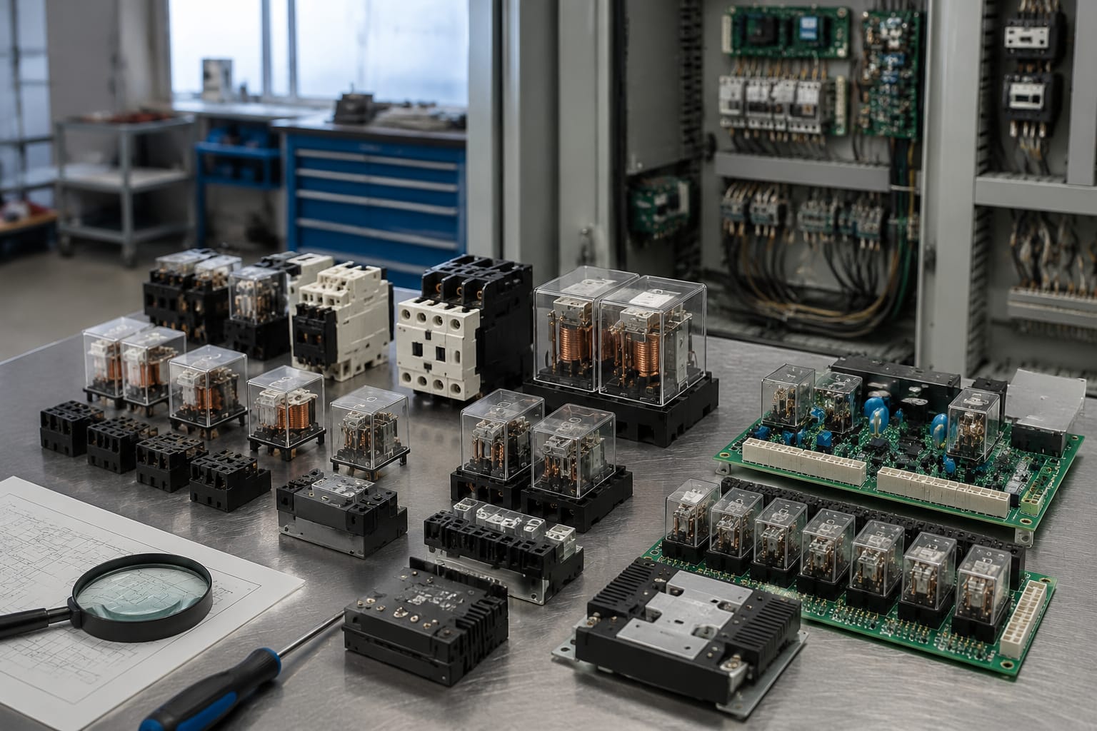
An elevator relay is an electrically operated switch used to pass, interrupt or monitor control signals and power within an elevator system. A faulty relay can cause intermittent operation, door faults, safety-chain interruptions, levelling problems or a complete shutdown, but the relay itself is not always the root cause.
Before replacing an elevator relay, identify its circuit function, verify the coil voltage and contact ratings, inspect associated wiring and board damage, and confirm the replacement is compatible with the controller or relay board revision. These checks reduce the risk of replacing a sound component while leaving the underlying fault in place.
What elevator relays control
Elevators use relays to separate low-voltage control logic from higher-current loads, to provide electrical isolation, and to create monitored switching paths. Depending on the installation, an elevator relay may be a plug-in component in the controller cabinet, part of a relay board, or mounted in the car-top control panel, machine-room panel or door equipment.
Typical relay-controlled functions include:
- Car and landing door commands
- Door lock and door-zone circuits
- Safety-chain monitoring
- Motor contactor enable signals
- Brake control interfaces
- Travel direction and inspection control
- Levelling and re-levelling logic
- Car lighting, fan and alarm interfaces
- Emergency operation and fire-service-related control inputs
- Status signalling between boards, drives and the main controller
In older relay-based controllers, individual relays may perform much of the system logic. Modern microprocessor controllers generally use relays as output interfaces, safety interfaces or load-switching devices, while software handles the decision-making. This distinction matters during fault finding: an output relay may be working correctly even when the controller is not commanding it to energise.
A relay should therefore be assessed as part of its complete circuit. Check whether the coil receives the correct command voltage, whether its contacts switch correctly, and whether the load and return path are healthy.
Electromechanical and solid-state relays
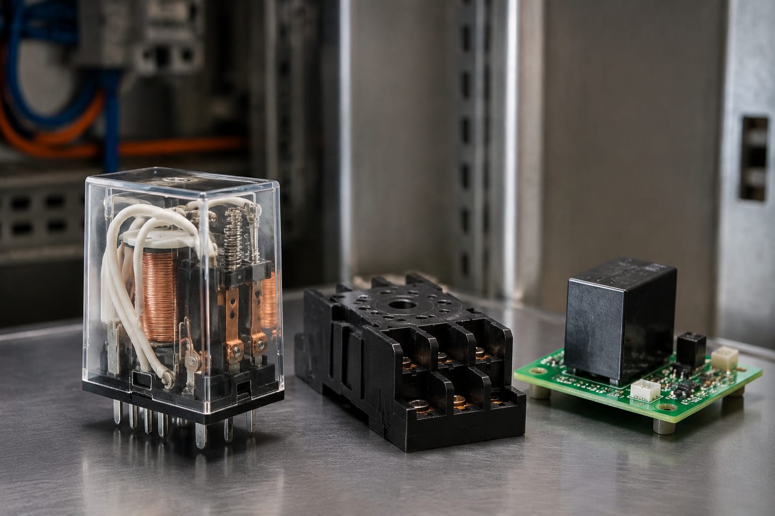
The two main elevator relay types are electromechanical relays (EMRs) and solid-state relays (SSRs). Both can control a circuit, but their construction, behaviour and failure modes differ.
| Feature | Electromechanical relay | Solid-state relay |
|---|---|---|
| Switching method | Physical moving contacts operated by a coil | Semiconductor switching device |
| Audible operation | Often clicks when energised | Silent |
| Contact wear | Contacts can pit, burn, stick or oxidise | No mechanical contacts |
| Heat generation | Usually low at the relay body, depending on load | Can generate significant heat under load |
| Leakage current | Normally open circuit when off, apart from contact condition | May pass a small off-state leakage current |
| Best suited to | General control, interlocking and moderate switching duties | Frequent switching and selected AC loads |
| Common failure mode | Open coil, welded contacts, high contact resistance, mechanical sticking | Shorted output, open output, overheating or control-input failure |
Electromechanical relays
An electromechanical elevator relay has a coil that creates a magnetic field when energised. This moves an armature and changes the state of its contacts. A relay may have normally open (NO), normally closed (NC) or changeover contacts.
These relays are widely used because they are straightforward to test, provide physical isolation between coil and contacts, and can be selected for many coil voltages and contact arrangements. However, their moving parts and contacts wear over time.
Contact condition is particularly important in safety and door circuits. A relay may click and appear to operate, yet its contacts may have excessive resistance, unstable continuity or heat damage that causes intermittent faults under load.
Solid-state relays
Solid-state relays use semiconductor components instead of moving contacts. They can switch rapidly and quietly, but they must be correctly matched to the load type, voltage, current and heat-dissipation requirements.
An SSR should not be treated as a direct substitute for an electromechanical relay simply because its nominal current rating looks suitable. Its switching characteristics, leakage current, control input, load voltage type and failure behaviour must all suit the circuit. Some safety-related or monitored applications require a specific relay design and feedback arrangement; replacing it with a different technology can alter how the controller detects a fault.
For either type, use the controller documentation, circuit diagram and original component specifications as the primary reference.
Relay boards in door and safety circuits
Relay boards group several relays and their associated terminals, connectors, fuses, indicators and protective components on one assembly. They are common in door-control interfaces, car-top panels and controller systems where multiple field signals must be connected to the main logic board.
A relay board may control or monitor inputs from door locks, door contacts, car-top devices, bypass functions or interface signals. It can also provide outputs to door operators, indicators or other peripheral equipment.
For example, a door bypass control relay board for Otis elevator parts is relevant only where the installed equipment and circuit function match the specified board. A bypass-related board is not a general-purpose replacement for an unrelated door or safety relay board.
Car-top relay boards often form part of the connection between travelling-cable signals, inspection controls and car equipment. When sourcing a replacement, the elevator car-top relay board for KCE/KONE lift parts illustrates the level of application-specific identification required: board function, manufacturer family, connector layout and revision all need verification.
Why safety and door circuits need extra care
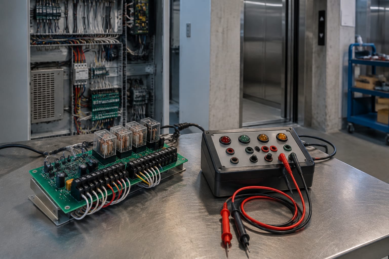
Door and safety circuits are designed so that an unsafe or unverified condition prevents normal travel. A relay fault in these circuits can produce symptoms such as a car refusing to run, doors failing to close, intermittent lock faults or a safety-chain indication.
Do not bridge, permanently link out or defeat safety contacts to keep an elevator operating. A temporary diagnostic method, where permitted by the manufacturer’s procedure and carried out by competent personnel, is not the same as an operational workaround. The original safety function must be restored and verified before returning the lift to service.
Relay-board faults are also not limited to relays. Common issues include:
- Cracked solder joints beneath relay pins or connectors
- Heat-damaged tracks and terminal blocks
- Loose plugs, bent pins or poor connector retention
- Failed suppression diodes, varistors or fuses
- Moisture ingress and contamination
- Incorrect field voltage entering a low-voltage input
- Damage caused by a faulty external load
Replacing the board without checking the external circuit can lead to the same failure occurring again.
Common signs of relay failure
Relay faults are often intermittent at first. The symptom can change with temperature, vibration, duty cycle or supply-voltage stability. A clear diagnosis distinguishes a relay failure from a controller command issue, wiring fault or defective load.
Common signs include:
- A relay does not pull in when its coil is supplied with the correct voltage.
- The relay chatters, buzzes or repeatedly drops out.
- The relay is energised but the output circuit remains open.
- Contacts remain closed after the coil de-energises.
- The relay becomes unusually hot or shows discolouration.
- An elevator function works only occasionally, often after repeated attempts.
- A door operator, brake interface or other load receives an unstable supply.
- A controller reports a circuit fault even though visible contacts appear closed.
- A relay clicks but the related input or output is not detected.
- The same fuse blows after the relay is replaced or energised.
A click alone is not proof of correct operation. It only indicates that the armature may be moving. The contacts may still be burnt, contaminated, welded, mechanically damaged or incorrectly rated for the load.
Likewise, a relay that looks damaged may be a result rather than the cause. A shorted coil, overloaded output, failing contactor coil, seized door operator or incorrect supply voltage can overheat a relay or its board.
Check coil voltage and contact ratings
The coil rating tells you what voltage is required to operate the relay. The contact rating tells you what the relay can safely switch. Both must match the circuit requirements.
Start by reading the original relay label, board markings and wiring diagram. Record the full part number rather than relying on the relay’s physical size or colour.
Coil checks
Confirm:
- Coil voltage, such as 24 V DC, 48 V DC, 110 V AC or another specified value
- AC or DC coil type
- Coil polarity where a DC relay includes an internal diode or indicator
- Coil resistance or expected current, where the manufacturer provides this information
- The actual voltage at the coil terminals while the circuit commands operation
A 24 V DC relay and a 24 V AC relay are not interchangeable. Nor should a relay with a suppression diode be installed without checking polarity and the controlling output. Reversed polarity can create a short circuit on some designs.
Low coil voltage can cause chatter or incomplete operation. High coil voltage can overheat the coil and shorten relay life. If measured coil voltage is wrong, investigate the controller output, power supply, field wiring and any series safety contacts before changing the relay.
Contact checks
Contact ratings require more than one comparison. Confirm:
- Maximum switching voltage
- Maximum continuous current
- AC or DC load rating
- Load type: resistive, inductive, motor, solenoid or electronic
- Number and arrangement of contacts: NO, NC, changeover, double-pole and so on
- Required isolation or creepage characteristics where specified
- Inrush current, particularly for coils, transformers and door-related loads
DC inductive loads deserve particular attention. Breaking DC current can create sustained arcing, and a contact rating suitable for AC may not be suitable for the same DC voltage and current. Suppression components may be required, but use only the arrangement intended for the circuit because suppression can change release timing.
Do not assume a higher current rating makes a relay universally suitable. The pin layout, contact configuration, coil consumption, timing, approvals and board compatibility may still be wrong.
Diagnose the circuit before replacement
A structured diagnosis prevents unnecessary replacement and helps protect the new component. Isolate the elevator safely, follow the site procedure and use qualified personnel with suitable test equipment.
A practical sequence is:
- Record the fault condition. Note controller messages, indicator states, relay labels and which function has failed. Intermittent faults are easier to investigate when the conditions are documented.
- Use the circuit diagram. Identify the relay coil terminals, contact terminals, supply source, input or output being controlled, and every series device in the circuit.
- Inspect before testing. Look for heat marks, loose terminals, contamination, broken wires, damaged plugs and signs of arcing. Check that relays are fully seated in their bases.
- Verify the coil command. With appropriate safe test methods, establish whether the correct rated voltage reaches the coil when the relay should operate. No command voltage usually points upstream of the relay.
- Test coil integrity. With power isolated, measure coil resistance where appropriate and compare it with known-good data or an identical confirmed component. An open coil is a clear failure; a very low reading may indicate a shorted coil.
- Test contact condition. Check continuity and contact resistance in the de-energised and energised states. Test under the relevant operating condition where safe and appropriate, because a no-load continuity test may not reveal a high-resistance contact.
- Check the connected load. Measure for short circuits, excessive current or mechanical binding. A defective load can weld relay contacts or damage a board output.
- Confirm controller logic. If the relay and field circuit test correctly, investigate whether the controller is withholding its command due to another input, safety condition or stored fault.
On PCB-mounted relays, inspection of solder joints can be useful, but avoid damaging board tracks through unnecessary rework. If the board is multi-layered, conformally coated or safety-related, replacement of the complete approved board may be more reliable than component-level repair.
Match boards, connectors and revisions
A replacement relay board must match more than its general description. Two boards can look similar while using different connector pin-outs, relay assignments, firmware expectations or supply arrangements.
Before ordering a board, verify:
| Compatibility check | What to compare |
|---|---|
| Original part number | Full number, suffixes and manufacturer markings |
| Board revision | Revision code, issue number or PCB artwork identifier |
| Controller family | Exact controller and supported application |
| Connector layout | Plug type, keying, pin count and pin assignments |
| Relay positions | Relay count, contact function and terminal mapping |
| Input and output voltages | Field supply, logic supply and coil voltages |
| Door or safety application | Function of each monitored and switched circuit |
| Physical installation | Mounting holes, enclosure clearance and terminal orientation |
Photographs are helpful for a preliminary comparison but should not be the only compatibility check. Connector faces can look identical while being pinned differently, and a later board revision may require matching changes elsewhere in the system.
For systems that use an interface assembly, compare the original identifier and circuit role against the elevator interface relay board range before treating it as a potential replacement. The exact product specification must still be confirmed against the installed equipment.
For B2B sourcing teams, send the original part number, clear photographs of both sides of the component, connector details, board revision and the controller model. These details allow a distributor or supplier to assess fitment more accurately than a generic description such as “elevator relay board”.
Kelevator supplies multi-brand elevator spare parts for B2B importers, distributors, maintenance contractors and OEM buyers. For a board or relay requirement, the useful starting information remains the same: original identification, application, revision and electrical specifications.
Test the system after replacement
Replacement is complete only after the affected circuit and the elevator’s safety functions have been tested according to the manufacturer’s procedure and the site’s maintenance requirements.
After fitting the correct component:
- Confirm all connectors, relay bases, terminals and retaining clips are properly seated.
- Check that no wires are trapped, strained or connected to the wrong terminals.
- Restore power using the appropriate safe procedure.
- Verify that the replacement relay or board has the correct supply voltage.
- Test the original fault condition first.
- Run the relevant functional checks, such as door operation, lock monitoring, levelling, inspection operation or normal travel, according to the circuit affected.
- Confirm that fault indications clear only when the underlying condition is genuinely corrected.
- Observe the component for heating, chatter, unstable operation or repeated fuse failure.
- Record the replacement part number, board revision, fault finding performed and test result.
A relay replacement can expose a separate underlying problem. For example, restoring a door relay output may reveal a worn door lock contact, damaged travelling cable core or intermittent door-operator input. Treat new symptoms as diagnostic information, not evidence that the replacement part is defective.
Avoid leaving an elevator in service after only a brief “it moved once” test. Intermittent relay and connection faults may reappear after several cycles, changes in temperature or vibration. The scope of testing should reflect the circuit’s function and the safety implications of failure.
FAQ
Can an elevator relay be replaced with an equivalent relay?
Only if the electrical, mechanical and functional characteristics match the original application. Confirm coil voltage and type, contact arrangement, AC/DC ratings, load duty, pin configuration, suppression components, timing and any manufacturer-specific requirements. For relay boards, board revision and connector pin-out are equally important.
Why does an elevator relay chatter?
Chatter commonly results from low or unstable coil voltage, a poor supply connection, an intermittent control signal, a failing coil or a voltage drop through series contacts. Replacing the relay without measuring the coil supply can leave the fault unresolved.
Can a welded relay contact cause an elevator to stop?
Yes. Welded contacts can keep an output or status circuit active when it should release. In controlled or monitored circuits, this can prevent the controller from receiving the expected feedback and can take the elevator out of service. The cause of welding, such as excessive load current or inadequate suppression, should also be investigated.
Is it safe to swap relays for fault finding?
Swapping identical relays can sometimes help isolate a fault, but only where their complete part numbers, ratings, contact arrangements and circuit functions are confirmed as identical. Do not move relays between safety-critical positions or substitute unknown relays merely because they fit the socket.
For a replacement decision, first identify the relay or board by its complete marking, then verify the circuit function, ratings, revision and connector arrangement against the installed elevator equipment.
Related product references
For practical catalog examples related to this topic, review [Door Bypass Control Relay Board OTIS elevator parts lift accessories](/products/door-bypass-control-relay-board-otis-elevator-parts-lift-accessories/), [Elevator car top relay board KCE KONE lift parts](/products/elevator-car-top-relay-board-kce-kone-lift-parts/), and [interface board relay board lift parts elevator accessories](/products/interface-board-relay-board-lift-parts-elevator-accessories/). Confirm the exact model, dimensions, ratings, and connectors before ordering.