
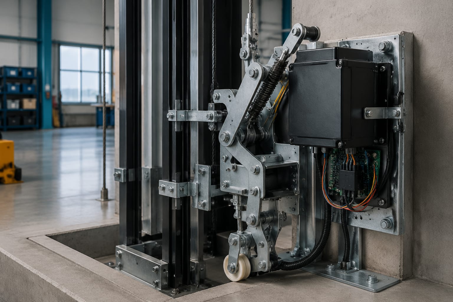
Lift safety gear is a mechanical stopping device fitted to a lift car, and in some designs to a counterweight, to prevent uncontrolled movement. It works with an overspeed governor, governor rope and linkage to grip the guide rails when a specified unsafe condition is detected.
It is not a routine consumable part. Correct selection, adjustment and testing depend on the lift’s rated speed, mass, guide rails, governor arrangement and original design. A replacement that looks similar can be incompatible or create a serious safety risk.
How lift safety gear stops the car
Lift safety gear normally sits in the car sling or safety frame, close to the guide rails. Under normal operation, the gripping components remain clear of the rail faces and do not affect travel.
When the car exceeds the governor’s trip speed, the overspeed governor grips its rope. Continued movement of the car causes the governor rope to operate the mechanical linkage connected to the safety gear. The linkage drives wedges, rollers or clamping elements against the guide rails, creating a controlled stop or an immediate grip, depending on the type of gear.
The safety gear is only one part of a protective system. The full stopping sequence generally involves:
- The governor detecting excessive speed.
- The governor gripping the governor rope.
- The rope transmitting movement to the car linkage.
- The linkage applying the safety gear to the rails.
- Electrical safety contacts signalling the controller and preventing normal operation until the condition has been assessed and reset.
The exact sequence differs by lift design. On some installations, an electrical overspeed or safety-circuit signal stops the drive before the mechanical safety gear is applied. This does not remove the need for the mechanical gear; electrical and mechanical protection perform different functions.
A damaged rail, seized linkage or incorrectly adjusted governor can prevent the system from behaving as designed. For that reason, lift safety gear must always be assessed as part of the complete governor-to-rail system.
Governor, rope, linkage, and safety gear

The governor, rope, tension device and safety gear must be compatible as an assembly. Replacing only the visible gripping unit without confirming the surrounding equipment is a common source of errors.
Overspeed governor
The overspeed governor is typically mounted in the machine room or at the top of the shaft, although arrangements vary. Its rope travels with the lift car and passes around a tension sheave at the lower end of the shaft.
At its calibrated trip speed, the governor grips the rope. It may also operate an electrical switch that opens the safety circuit. The specified trip speed is not interchangeable between lifts of different rated speeds.
Confirm the governor manufacturer, model, pulley diameter, rope size, trip direction and trip-speed setting before changing a governor, governor rope or related component.
Governor rope and tension arrangement
The governor rope transmits force to the safety mechanism. Its diameter, construction, termination method, tension and routing affect operation. Wear, corrosion, broken wires, contamination, incorrect tension or a damaged tension sheave can alter how reliably the gear engages.
A rope that is not suitable for the governor groove may slip rather than transmit the required force. Conversely, an unsuitable rope can accelerate groove wear. Treat the rope and governor sheave as a matched application, not as independent catalogue items.
Safety linkage
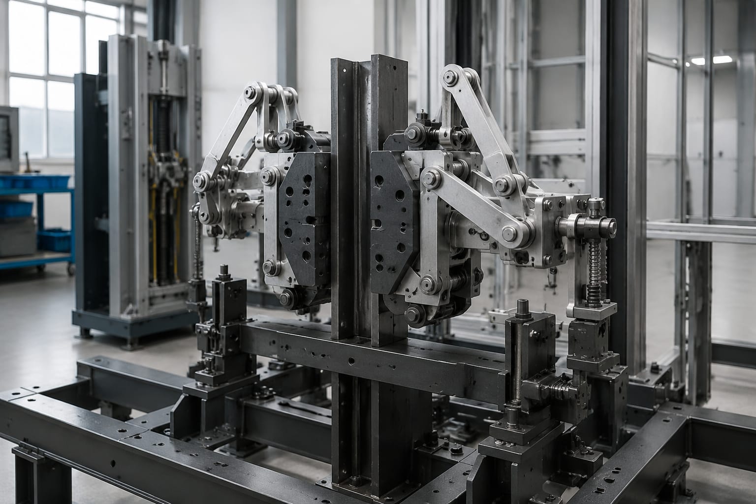
The linkage transfers governor-rope movement to both sides of the safety gear. It may include rods, levers, crossheads, springs, pivots and reset components. It must apply the gear evenly to both guide rails.
Typical problems include:
- Stiff or seized pivots caused by corrosion or inadequate lubrication where lubrication is specified.
- Bent rods or levers after an activation or impact.
- Lost motion caused by worn pins, bushes or joints.
- Incorrect rod length or adjustment.
- Missing return springs, split pins, clips or locking hardware.
- Uneven operation between the left- and right-hand safety blocks.
Do not compensate for a damaged linkage by simply increasing adjustment. The cause of uneven movement needs to be identified first.
Electrical monitoring
Safety gear installations commonly include contacts that report movement or prevent normal running once the safety gear has operated. Switch brackets, actuators and wiring must remain correctly positioned and protected from mechanical damage.
Related components can include [lift brake-lock micro-switch brackets and accessories](/products/brake-lock-micro-switch-bracket-shrapnel-lift-accessories-elevator-spare-parts/) and [micro-movement detection switches for lift applications](/products/brake-micro-movement-detection-switch-lift-parts-elevator-accessories/). These parts may support safety monitoring, but they are not substitutes for a correctly specified mechanical safety gear assembly.
Progressive versus instantaneous types
The key difference is the way the safety gear stops the lift car after it grips the rails. Selection is determined by the original lift design, rated speed, rated load and rail specification. It is not a matter of choosing the “stronger” option.
| Feature | Progressive safety gear | Instantaneous safety gear |
|---|---|---|
| Stopping action | Applies a braking force over a distance | Grips the rails with very limited stopping travel |
| Typical mechanism | Wedge or roller arrangement with controlled friction | Rigid wedge or clamp action |
| Suitability | Commonly used where a controlled deceleration is required | Generally limited to applications and speeds for which abrupt stopping is acceptable |
| Rail condition sensitivity | Requires correctly matched rail surfaces and adjustment | Also relies on compatible rails and correct mechanical condition |
| Inspection focus | Wedge condition, springs, braking surfaces, linkage balance | Gripping surfaces, clearances, linkage condition and signs of impact |
| Replacement approach | Match the original approved specification exactly | Confirm that it is the intended type; do not convert types casually |
Progressive safety gear
Progressive gear is designed to develop braking force progressively as it moves along the rails. This reduces the shock of a safety-gear operation compared with an immediate rigid grip.
Its operation depends on the wedge geometry, springs, friction surfaces and guide rail characteristics. Rail lubricant, paint, corrosion, contamination, excessive wear or mismatched rail profiles can affect braking behaviour. Adjustment is therefore not a simple clearance-setting exercise.
Progressive safety gear is widely associated with higher-speed or higher-capacity applications, but the governing requirement is the approved design for the particular lift. A speed assumption alone is insufficient for selection.
Instantaneous safety gear
Instantaneous safety gear grips the guide rails rapidly with little or no progressive braking travel. It may be appropriate for certain lower-speed arrangements where the original design permits it.
Because it stops abruptly, an instantaneous device is not automatically suitable for a lift simply because it shares a rail size or mounting pattern. Converting a progressive system to instantaneous gear, or the reverse, changes the safety behaviour and should only happen through an engineered, compliant modernisation design.
Do not select by appearance
Safety blocks can look alike while differing in important details, including:
- Guide rail size and rail-head profile.
- Permitted mass and rated speed.
- Mounting-hole centres and orientation.
- Direction of travel and actuation.
- Required governor-rope pull or linkage travel.
- Reset method.
- Applicable type approval, manufacturer documentation or certification marking.
A photograph helps identify a part, but it is not enough to confirm safe interchangeability.
Car and counterweight applications
The car safety gear protects the lift car when the governor system detects an overspeed condition or another applicable triggering event. It is normally installed as a matched left- and right-hand arrangement in the car sling.
Counterweight safety devices are used on some lift designs, particularly where the design, travel arrangement or applicable requirements call for protection against counterweight overspeed or unintended movement. Their activation arrangement may differ from the car’s governor-operated safety gear.
When reviewing a counterweight application, establish:
- Whether the installation has a counterweight safety device at all.
- What triggers it: governor action, rope failure protection, an electrical device or another approved mechanism.
- The counterweight frame design and fixing arrangement.
- The guide rail section, rail condition and available stopping distance.
- Whether work on the counterweight affects balancing, roping or shaft clearances.
Never assume a car safety gear can be installed on a counterweight frame. The loads, geometry, triggering arrangement and certification requirements can differ materially.
Common inspection findings
Routine maintenance should include a visual and functional assessment at intervals required by the lift’s maintenance plan, site risk controls and applicable South African requirements. A full activation test is a specialist activity and should not be improvised during ordinary servicing.
Common findings include the following.
Corrosion and contamination
Moisture, dust, construction debris and oil can accumulate around safety gear and linkage. Corrosion can seize pivots or springs, while oil on rail gripping surfaces can alter braking performance. Water ingress in a shaft also needs investigation beyond cleaning the affected component.
Worn, damaged or altered parts
Look for worn rollers, scored wedges, cracked housings, damaged springs, distorted levers, loose fasteners and non-original repairs. Grinding, welding or machining a safety component without the manufacturer’s approved process can change its operating characteristics.
Guide rail defects
Safety gear grips the guide rails, so the rail condition is part of the safety function. Check for loose fishplates, damaged rail faces, corrosion, incorrect alignment, excessive lubricant and evidence of previous safety-gear engagement.
A new safety block will not correct a rail problem. It may instead produce an unpredictable result when activated.
Incorrect reset condition
After a safety-gear operation, the mechanism must be released and reset in accordance with the manufacturer’s procedure. A lift returned to service with an incompletely reset device may not run, may produce safety-circuit faults, or may be left in a condition that requires immediate attention.
Electrical safety-circuit faults
A safety contact can be correctly fitted but electrically unreliable because of misalignment, a broken actuator, damaged cable or loose terminal. Control-system diagnosis may also involve components such as a [Toshiba elevator safety circuit relay board](/products/toshiba-elevator-safety-circuit-relay-board/) where that board is relevant to the installed system. The controller component, wiring and mechanical safety device should be traced as one fault path.
Identification data for replacement
Obtain complete identification before requesting a replacement lift safety gear. This reduces the risk of receiving a part that physically fits but does not meet the original design requirements.
Provide the following information where available:
- Safety gear manufacturer, model and complete markings.
- Clear photographs of both sides, mounting faces, labels and linkage connection.
- Whether the unit is left-hand, right-hand, upper, lower, car-side or counterweight-side.
- Lift manufacturer, controller details and lift serial or installation reference.
- Rated load, rated speed and car mass if known.
- Guide rail manufacturer, rail designation and rail-head dimensions.
- Governor manufacturer, model, rope diameter and governor trip data.
- Mounting dimensions, bolt sizes and hole centres.
- Linkage arrangement, rod lengths and reset method.
- Reason for replacement, such as corrosion, damage after activation, missing parts or planned modernisation.
- Information from the maintenance record about prior safety-gear activation or alterations.
Where a marking plate is unreadable, do not estimate the rating from the size of the component. Compare original drawings, parts lists, commissioning documentation and verified lift measurements.
For legacy lifts, an exact original part may no longer be readily identified. In that case, a competent lift engineer should determine whether an approved equivalent exists or whether the safety system needs a properly designed upgrade rather than a one-for-one substitution.
Why adjustment and testing require specialists
Safety gear adjustment and testing involve stored mechanical force, suspended equipment, shaft access and a device intended to stop a moving lift. Incorrect work can expose technicians and passengers to serious risk.
Specialist work is required because it may involve:
- Verifying governor trip operation and rope gripping.
- Setting linkage travel and ensuring simultaneous application on both rails.
- Confirming the safety gear matches the car mass, speed and guide rails.
- Checking rail condition and fixings before any test.
- Managing controlled test conditions and preventing unintended lift movement.
- Inspecting for damage after activation.
- Restoring the safety circuit, reset mechanism and normal operation.
- Recording the work and determining whether further corrective action is needed.
Do not test safety gear by bypassing electrical interlocks, inducing overspeed in an uncontrolled way, or forcing linkage with the car occupied. Likewise, do not release an activated device until the car is secured and the cause of activation is understood.
The relevant lift regulations, inspection requirements, site procedures, manufacturer instructions and competent-person responsibilities should guide the work in South Africa. Where they differ, the applicable legal and project requirements take precedence.
Documentation after safety work
Good documentation makes later maintenance safer and supports accurate sourcing. After inspection, repair, replacement or testing, record the equipment identity, condition found, work completed and the basis for returning the lift to service.
A useful record should include:
- Lift identification and location within the property.
- Date, technician or competent person, and scope of work.
- Safety gear, governor and governor-rope identification details.
- Measured settings and adjustments, where applicable.
- Parts replaced, including part numbers and traceable supplier details.
- Condition of guide rails, linkage, tension arrangement and electrical contacts.
- Test method, outcome and any limits on the test performed.
- Defects corrected and defects still requiring action.
- Reset procedure completed and final operational status.
- Photographs of markings, damage and completed installation where useful.
Keep replacement packaging, certificates or manufacturer documentation with the lift records when supplied. These documents can be valuable when the next contractor needs to confirm compatibility or investigate an event.
FAQ
Can lift safety gear be reused after it has operated?
It depends on the manufacturer’s instructions, the type of gear and the condition after activation. A specialist should inspect the safety blocks, linkage, rails, governor and rope before deciding whether components can be reset and retained. Damage may not be obvious externally.
Is a governor switch the same as lift safety gear?
No. A governor switch is an electrical device that can open a safety circuit. Lift safety gear is the mechanical rail-gripping device that stops the car or, in some systems, a counterweight. Both may form part of the same protective arrangement.
Can a maintenance team replace safety gear with a similar-looking unit?
Not safely without confirming the full specification. Rated speed, mass, rail profile, mounting geometry, governor pull and certification details must match the approved design.
What should be done after a safety-gear activation?
Secure the lift, keep it out of service, establish why the device operated, inspect the complete system and follow the approved reset and test procedure. Returning the lift to normal service without finding the cause can leave a recurring fault unresolved.
For sourcing or planned replacement, compile the identification data and maintenance history first. Kelevator supplies multi-brand lift spare parts to B2B importers, distributors, maintenance contractors and OEM buyers; complete technical information helps establish whether a requested component is suitable for the existing installation.