
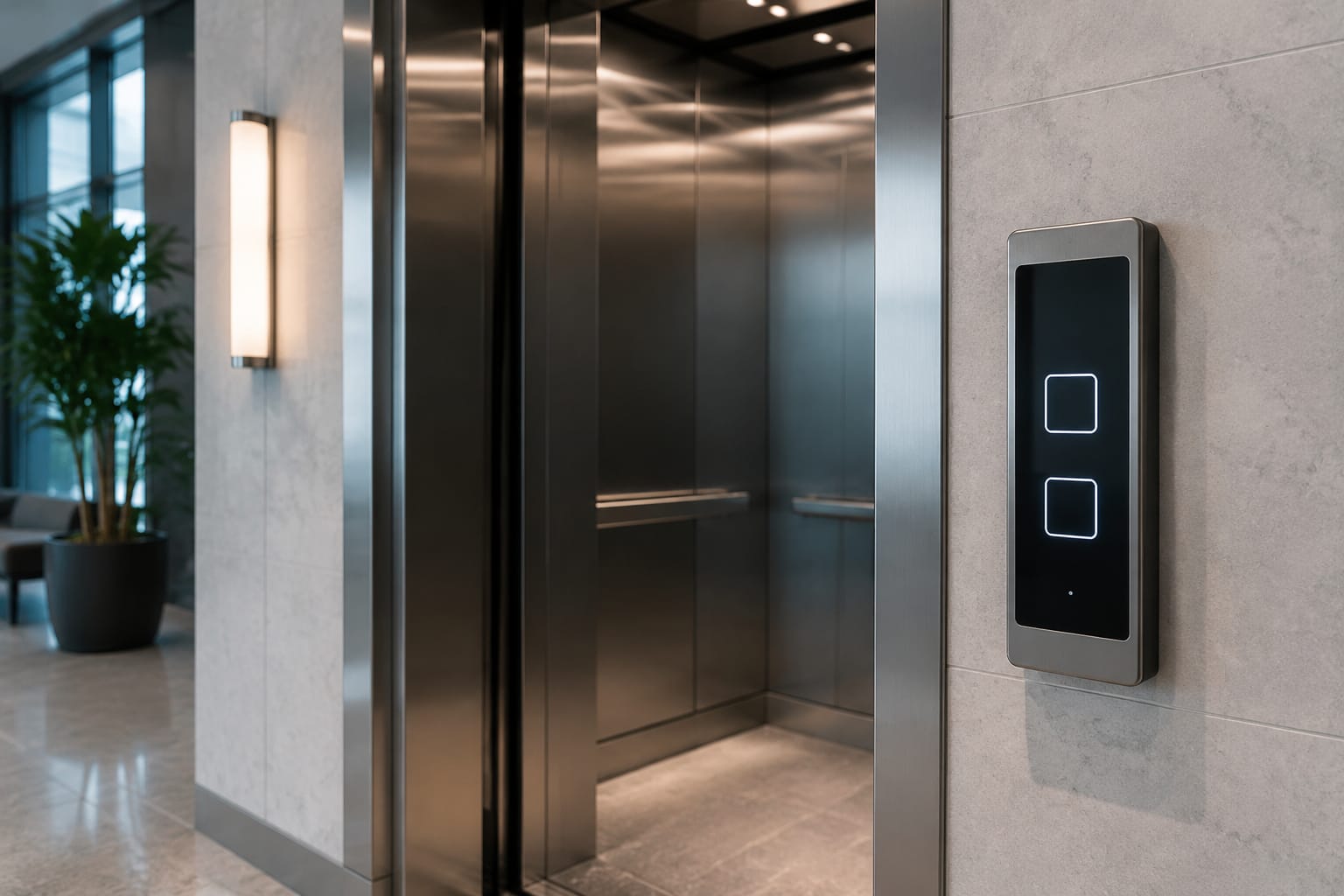
An elevator touch panel can improve car appearance, simplify cleaning and provide flexible display options, but it is not a universal replacement for conventional push buttons. A successful upgrade depends on the panel’s sensing method, controller interface, physical fitment, accessibility provisions and behaviour during a fault or power interruption.
For a new panel or retrofit, first identify the existing controller, the number and type of floor calls, operating voltage, communication method, mounting dimensions and emergency functions. Then assess the touch surface in the real environment, including glare, vandalism risk, damp cleaning practices and the way users wearing gloves or with reduced dexterity will operate it.
How elevator touch panels work
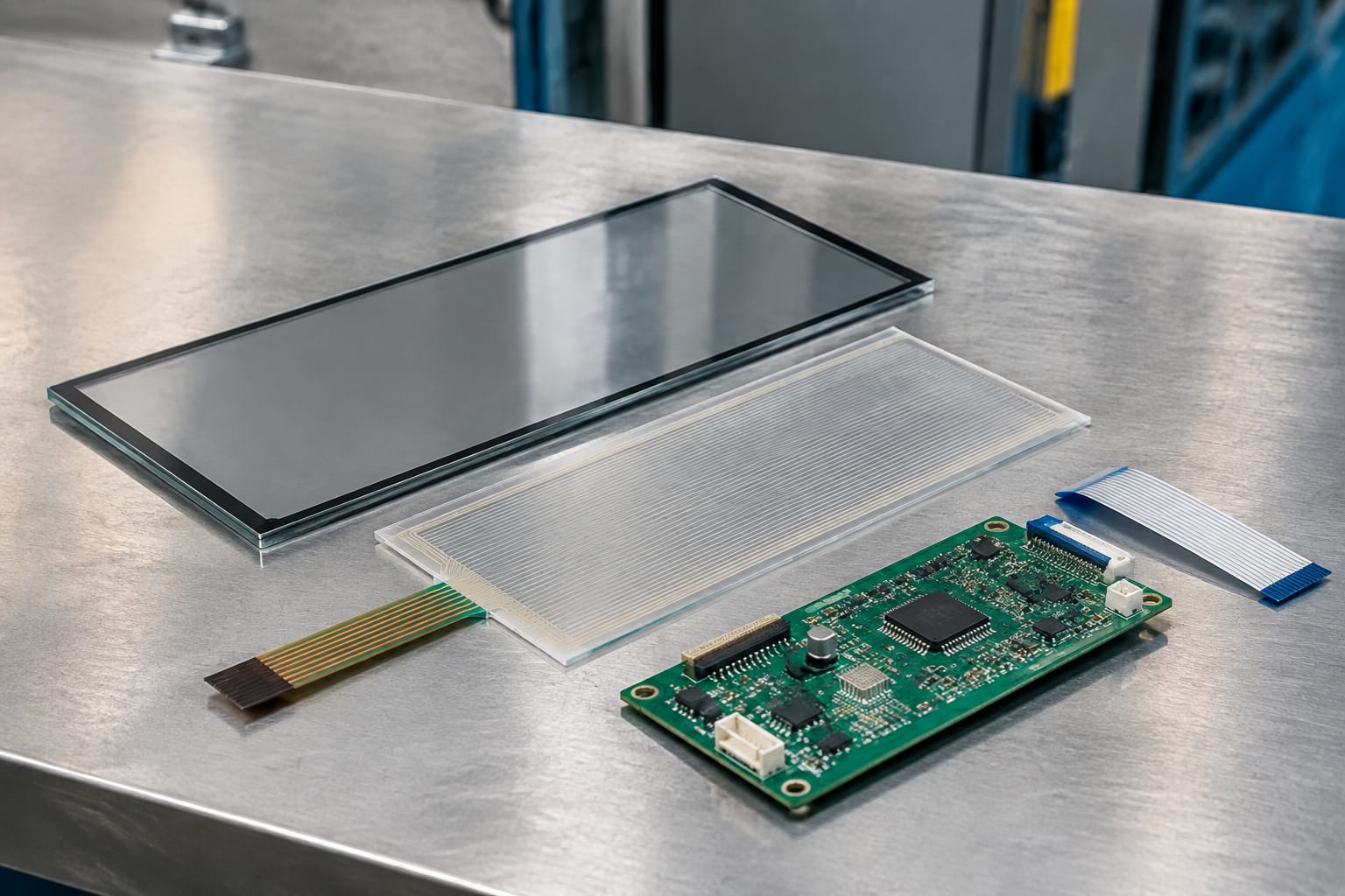
An elevator touch panel combines a user-facing surface with electronics that translate a press into an elevator call. The visible surface may be glass, acrylic, polycarbonate or a protected display layer. Behind it, a sensor detects the user input and sends a signal to the panel electronics, which in turn communicates with the lift controller or a separate input board.
The main sensing methods are:
- Capacitive touch: Detects a change in an electrical field when a finger approaches or touches the surface. It supports a smooth glass-fronted appearance and can enable multiple layouts on a display.
- Resistive touch: Registers pressure when two conductive layers make contact. It can be operated with a finger, gloved hand or stylus, although the surface can be more prone to wear.
- Infrared or optical touch: Uses a sensor arrangement around the perimeter to detect interruption. This is less common for compact car operating panels because contamination and physical damage can affect performance.
- Projected button zones: A display or printed face shows call locations, while electronics identify the selected zone. The panel may have fixed or configurable floor labels.
A touch panel is only one part of the command chain. It must correctly register the intended call, give the passenger clear feedback, pass a valid signal to the controller and remain reliable in the installation environment. A visually modern panel with an unsuitable interface may not operate safely or consistently.
Before selecting one, establish whether the panel is intended for a car operating panel, landing station, destination-control terminal, information display or a combined unit. These applications have different wiring, user-interface and reliability requirements.
Touch buttons versus mechanical buttons
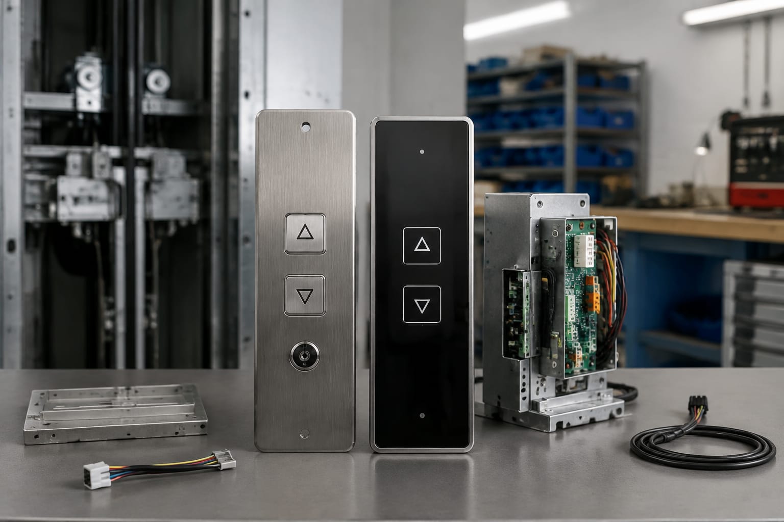
Mechanical push buttons remain common because their action, tactile feedback and fault modes are familiar to passengers and technicians. Touch panels offer a different set of benefits and constraints, particularly when a project involves car refurbishment or a more configurable interface.
| Consideration | Elevator touch panel | Mechanical button panel |
|---|---|---|
| User feedback | Usually visual, audible or both | Physical travel and often an illuminated ring |
| Appearance | Flush, contemporary surface with flexible graphics | Defined individual buttons and engraved legends |
| Cleaning | Few gaps around controls | Requires cleaning around button edges |
| Accessibility | Needs deliberate tactile, audible and visual design | Tactile response is inherent, but labelling still matters |
| Vandalism and impact | Depends heavily on face material and installation | Individual buttons can be robust but may be prised or damaged |
| Layout changes | Possible on programmable displays | Usually requires relabelling or replacement components |
| Fault isolation | May involve panel electronics, software or communications | Individual button and lamp circuits can often be tested separately |
| Retrofit complexity | Can be high where interfaces are proprietary | Often simpler when replacing like for like |
A touch interface should not be selected solely for appearance. Passengers must be able to find, understand and confirm a selection quickly. On a conventional mechanical panel, button travel provides immediate proof of input. A touch panel needs an equally clear alternative, such as a distinct illumination change, audible confirmation or both.
Mechanical buttons may also be the better option where the lift serves a harsh or poorly supervised environment, where glove use is routine, or where the existing controller accepts only conventional discrete inputs. Conversely, a touch panel can be appropriate where a flush finish, clear status display and configurable interface offer practical value.
For projects using touch-board components, compare the connector type, dimensions, voltage and controller requirements against the existing equipment. An [ID elevator touch button board](/products/id-elevator-touch-button-board-3300-lift-parts/) is a component-specific option rather than evidence of universal interchangeability.
Display and user-interface options
The panel display and interface should make routine use obvious before adding decorative features. At minimum, users need to identify their floor, see whether a call has registered and understand basic lift status. The interface should remain legible from a normal standing position and under the lighting conditions in the car.
Fixed legends, displays and hybrid designs
A fixed graphic touch panel shows permanent floor and function labels. It can suit buildings with a stable floor arrangement and may be simpler to maintain than a fully programmable screen.
A display-based panel can show dynamic floor names, car position, direction arrows, messages and service information. It allows the layout to change if tenants, floor names or access arrangements change. However, the project must account for software configuration, display brightness, replacement support and a clear fallback state if the display or communications fail.
A hybrid design uses mechanical emergency controls alongside touch-operated floor selections. This can provide a more direct operation for functions that must be readily identifiable, while retaining a modern presentation for standard calls.
Interface details that affect usability
Review these details on drawings, samples or a test unit:
- Floor identification: Use unambiguous labels. Basement, ground and parking levels should follow the building’s established convention.
- Confirmation: Each accepted touch should produce prompt visible feedback. An optional tone should be distinct without being intrusive.
- Contrast and glare: Dark glass and low-contrast lettering can look refined but become difficult to read under reflected light.
- Touch target size and spacing: Small, tightly packed zones increase incorrect selections, particularly on busy passenger lifts.
- Status information: Direction, car position and out-of-service messages should not obscure the call interface.
- Language and symbols: Use clear symbols where appropriate and ensure any text suits the building’s users.
- Cleaning resistance: Confirm which cleaning products are permitted. Abrasive cloths and unsuitable chemicals can damage coatings or reduce visibility.
An LCD panel can provide separate information or status functions where its electrical and physical requirements match the system. For example, assess the stated documentation and connection requirements for a [Monarch system LCD display panel](/products/monarch-system-lcd-display-panel-lift-parts-elevator-accessories/) before treating it as an interchangeable replacement.
Common touch-panel fault symptoms
Most touch-panel problems fall into one of four areas: sensing, power, communication or configuration. The observed symptom is useful, but it does not by itself prove that the touch panel is defective. Wiring, earthing, controller inputs, door-zone conditions and building power quality can produce similar complaints.
| Symptom | Likely causes to investigate | Practical first checks |
|---|---|---|
| A zone does not respond | Failed sensor area, damaged face, loose connector, incorrect configuration | Compare with other zones, inspect the surface and connector, verify the mapped input |
| Calls register intermittently | Moisture, contamination, grounding issue, electrical interference, failing electronics | Clean using the approved method, inspect cable screening and earthing, monitor repeatability |
| Several or all zones fail | Loss of supply, disconnected harness, controller communication fault, panel processor fault | Check supply at the panel, fuses, connectors, network status and controller faults |
| Wrong floor is selected | Configuration error, shifted touch calibration, incorrect overlay or software mapping | Test every call against the panel layout and controller input assignment |
| Panel remains lit but accepts no input | Touch controller fault, frozen firmware, failed communication path | Record indicators and controller events before resetting or replacing parts |
| No illumination or display | Supply issue, backlight or display failure, harness damage | Measure the required supply and inspect connectors before condemning the display |
| False calls or repeated inputs | Moisture, conductive dirt, damaged surface, interference or controller interpretation issue | Isolate the panel where permitted, inspect the face and review event logs |
Do not rely only on a power-cycle reset. It can mask an intermittent fault and remove evidence that helps identify the cause. Record the panel status, controller fault codes, supply readings, date, conditions and affected floor calls before making changes.
Common mistakes include replacing a panel before checking the harness, assuming a similar-looking connector has the same pinout, and testing only one or two floor selections. A call that lights locally but is not acknowledged by the controller points to a different part of the chain than a dead touch zone.
Work on lift equipment should be undertaken by competent personnel using the site’s isolation, access and return-to-service procedures. Emergency and safety circuits require particular care; they should never be bypassed simply to prove a panel fault.
Controller and communication compatibility
Compatibility is the main technical risk in an elevator touch-panel upgrade. A panel may fit the cut-out and use a familiar connector while still being electrically or logically incompatible with the controller.
Older installations commonly use discrete, hard-wired inputs: each floor button corresponds to a separate input or call circuit. A compatible touch panel must provide the correct contact or signal behaviour for each call and for functions such as door open, door close, alarm, fan or attendant operation where fitted.
Newer systems may use serial communications, CAN-based networks or a manufacturer-specific protocol. In these cases, the controller expects particular messages, addressing and configuration. A generic-looking display panel cannot normally substitute for a proprietary network device without confirmed compatibility.
Compatibility checklist
Obtain and verify the following before ordering or installing:
- Controller make, model, software or board revision where available
- Existing panel part number and clear photographs of labels and connectors
- Car operating panel wiring diagram and connector pinout
- Supply voltage, current requirement, polarity and earthing arrangement
- Number of floors, open/close functions, key switches and access-control inputs
- Whether inputs are dry contacts, voltage signals, matrix-scanned or serial data
- Communication protocol, node address and terminating requirements where applicable
- Mounting cut-out, panel depth, fixing points and cable route
- Display size, resolution, brightness control and orientation where a display is used
- Required fire service, emergency communication and alarm arrangements
- Firmware, parameter tools or licensing required for configuration
Treat the original equipment documentation and verified measurements as the source of truth. Marketing images, panel shape and connector appearance are insufficient for a compatibility decision.
Where the project calls for a board in a defined product family, a [3300/3600 elevator touch button board](/products/elevator-touch-button-board-3300-3600-lift-parts/) may be relevant to a component comparison. Confirm the exact application, revisions and interface details with the technical documentation before specifying it.
Accessibility and emergency operation
A smooth touch surface does not automatically provide an accessible interface. Passengers with limited vision, reduced dexterity or sensory impairments may find a purely visual, flat panel harder to operate than conventional controls.
Accessibility should be designed into the panel rather than added as an afterthought. Consider:
- Clear visual contrast between labels, selected calls and the background
- Tactile markers, raised identifiers or a separate tactile control arrangement where required
- Audible confirmation that a valid call has been accepted
- Logical floor order and consistent placement of door-control functions
- Sufficiently large, well-spaced touch targets
- Readability for seated users and standing users of different heights
- A surface that remains understandable when sunlight, glare or reflections are present
Emergency functions need their own review. Alarm activation, emergency communication and any prescribed emergency controls must remain identifiable and operational under the applicable design, building and lift requirements. Do not assume a touch-only alarm function is acceptable simply because it can be shown on screen.
Confirm current requirements with the project’s lift professional, building representative and applicable South African regulations and standards. Requirements can vary with building type, the scope of work and whether the alteration is treated as maintenance, replacement or modernization.
Retrofit and modernization planning
A planned retrofit is more reliable than a cosmetic panel swap. Start by defining the operational problem: worn buttons, poor legibility, unavailable spares, a damaged car interior, a need for clearer information, or a controller modernization. The answer affects the appropriate scope.
Assess the existing installation
Survey the car operating panel and controller before finalising the design. Photograph the front and rear of the panel, measure the cut-out and depth, document every function, identify cable condition and note prior modifications. Check whether the existing car top, travelling cable and controller have enough spare cores or network capacity for the proposed equipment.
Also inspect the environment. High passenger traffic, public access, coastal humidity, dust, regular cleaning and unreliable building supply can influence the suitable face material, sealing, display specification and spare-parts strategy.
Choose the upgrade scope
A like-for-like component replacement can be appropriate when the controller and panel arrangement are sound and the required part is confirmed compatible.
A car operating panel refurbishment may replace the faceplate, indicators and inputs while retaining the controller. This requires careful mapping and full functional testing.
A controller-linked modernization can provide broader interface options, but it should include all associated commissioning work: wiring, parameters, displays, landing equipment integration and documentation. It should not be treated as just a front-panel replacement.
Avoid specifying a large, sophisticated display where the support path for replacement screens, configuration files or diagnostics is unclear. A simpler interface with verified replacement components may offer a better whole-of-life outcome.
Kelevator supplies multi-brand elevator spare parts to B2B importers, distributors, maintenance contractors and OEM buyers. For sourcing, provide the survey information above so that parts can be evaluated against the actual installation rather than selected on appearance alone.
Testing after installation
Testing should prove the complete operating chain, not merely show that the panel lights up. Perform work and testing under appropriate lift isolation and commissioning procedures, with the lift returned to service only after the responsible competent person is satisfied.
Use a documented test sequence:
- Inspect the installed panel for secure fixings, undamaged edges, correct connectors and strain relief.
- Verify supply voltage, polarity, earthing and communication connections against the approved documentation.
- Test each floor call individually and confirm the correct floor is registered by the controller.
- Test door controls, authorised-access calls, key switches and other fitted functions one at a time.
- Confirm call feedback is immediate, visible and, where fitted, audible.
- Check car position, direction and status messages for correct operation throughout travel.
- Test from normal user positions and assess glare, legibility and accidental-touch risk.
- Confirm emergency communication, alarm and related controls operate as required without defeating safety circuits.
- Repeat tests after normal door cycling and travel to identify intermittent cable or communication faults.
- Record the panel model, configuration, wiring changes, test results and any outstanding limitations.
Where software configuration is involved, retain the backed-up parameters and the final configuration record with the lift documentation. This reduces downtime when a panel, display or controller board later requires replacement.
A touch-panel upgrade is successful when it is clear to operate, compatible with the controller, maintainable by the service team and properly tested in the finished lift. Begin with a measured site survey and verified technical data, then select the panel and interface that meet the installation’s actual requirements.