
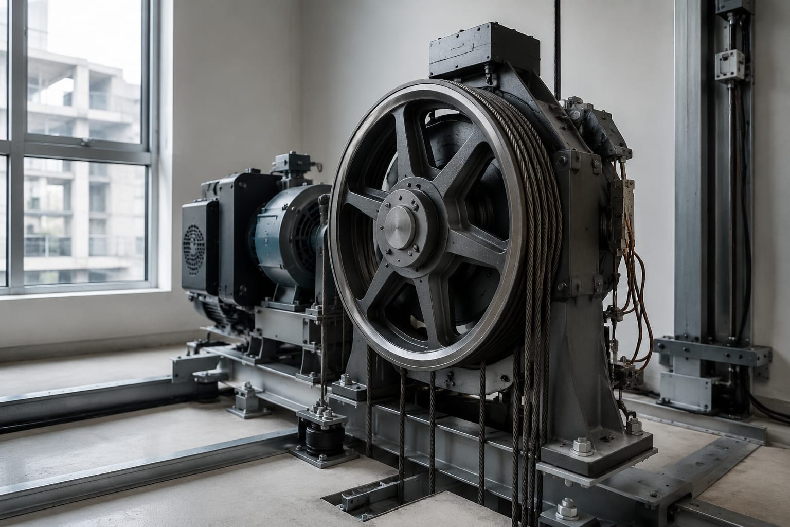
An elevator traction sheave transfers the machine’s rotational force to the suspension medium, allowing the lift car and counterweight to travel. Its condition is central to traction, ride quality and predictable stopping. When grooves wear, become uneven or do not match the rope or steel belt, the result can be slip, accelerated suspension wear and poor levelling.
A replacement elevator traction sheave cannot be selected by outside diameter alone. The groove form, pitch, shaft bore, keyway or hub interface, machine arrangement, suspension type and approved rope or belt specification must all match the application. Confirm these details against the machine documentation and the removed component before ordering.
How a traction sheave works
The traction sheave is the grooved wheel mounted on the traction machine shaft or connected through the machine’s designed hub arrangement. Suspension ropes or flat steel belts pass over it, with one side supporting the car and the other the counterweight or compensating arrangement.
As the motor turns the sheave, friction between the groove surface and the suspension medium creates enough grip to move the system. This friction is traction. It must be sufficient for normal running, acceleration, deceleration and emergency operating conditions, while still allowing the suspension medium to move through the grooves without excessive abrasion.
The balance between grip and wear matters:
- Too little traction can cause rope or belt slip, unstable stopping and loss of drive under demanding conditions.
- Excessive local pressure can damage rope wires, belt coatings or groove surfaces.
- Uneven groove wear changes load sharing between ropes or belts.
- A damaged or incorrectly sized sheave can create vibration, noise and premature bearing or suspension wear.
The sheave does not work in isolation. Correct traction depends on the complete suspension system, including car and counterweight masses, wrap angle, rope or belt construction, groove profile, tension equalisation, deflection sheaves and the machine’s control settings.
Steel-rope and steel-belt applications
Steel wire ropes and coated steel belts use different traction arrangements. A sheave intended for one should never be assumed suitable for the other merely because its diameter appears similar.
Steel wire-rope traction sheaves
Conventional lift systems commonly use several round steel wire ropes running in parallel grooves. Groove dimensions are designed for a specific nominal rope diameter and rope construction. The sheave must support each rope consistently so the load is distributed as evenly as possible.
The groove profile may be round, undercut, V-shaped or a manufacturer-specific variation. The specified profile affects traction and contact pressure. A rope that sits too deeply, rides too high or contacts sharp groove edges will not perform as intended.
For rope applications, key checks include:
- Nominal rope diameter and actual measured diameter
- Rope construction, lay and surface condition
- Number of ropes and groove count
- Groove pitch and alignment with deflection sheaves
- Groove wear consistency across the full sheave
- Tension balance between ropes
Flat steel-belt traction sheaves
Flat steel belts use sheaves with grooves or running tracks shaped for the exact belt width, thickness and coating system. The belt’s coating and embedded tensile elements are part of a matched suspension design. A conventional round-rope groove is not interchangeable with a steel-belt track.
Belt applications require particular attention to:
- Belt part number or approved suspension specification
- Belt width, thickness and running surface condition
- Number and spacing of belt tracks
- Track profile, edge support and contact surface
- Direction of travel and belt routing
- Manufacturer requirements for sheave replacement and inspection
For example, a [steel-belt traction sheave for 3300 elevator parts](/products/id-steel-belt-traction-sheave-3300-elevator-parts/) should be evaluated against the specific machine and belt configuration, rather than treated as a universal flat-belt component. Product naming alone is not enough to establish compatibility.
Groove profiles and traction conditions
Grooves control how the rope or belt contacts the traction sheave. Their profile influences traction, pressure distribution, heat generation and the ability of the suspension medium to seat correctly.
For round ropes, common profile families include round-bottom, undercut and V-type designs. Their exact geometry varies by manufacturer and application. An undercut can increase traction by changing the rope’s contact relationship with the groove, but it also requires careful control because the rope may experience higher local stresses.
For flat belts, the running tracks are normally designed to support the belt across its intended contact area without damaging its edges or coating. Grooves that are contaminated, scored or deformed can concentrate wear in a narrow section of the belt.
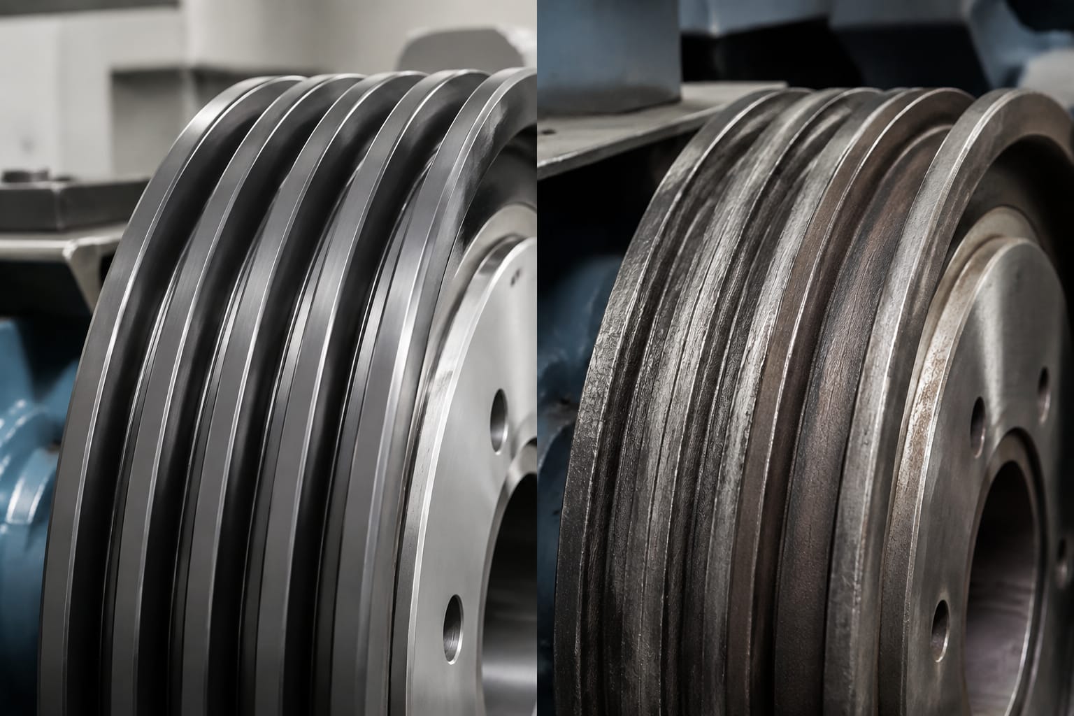
The condition of the groove surface is as important as its nominal shape. Problems to look for include:
| Condition | Likely effect | Practical response |
|---|---|---|
| Polished or glazed grooves | Reduced friction and a higher risk of slip | Investigate contamination, traction condition and wear limits |
| Uneven groove depth | Unequal rope loading | Measure all grooves and assess tension equalisation |
| Sharp edges or burrs | Rope-wire or belt-coating damage | Remove from service or rectify only where the approved procedure permits |
| Pitting, corrosion or scoring | Abrasive wear and irregular contact | Identify the moisture, debris or lubrication source before replacement |
| Incorrect groove pitch | Misalignment with ropes, belts or deflection sheaves | Verify dimensions and routing before fitting |
| Groove profile altered by machining | Changed traction characteristics | Use only an approved re-grooving method and profile |
Do not use general-purpose machining assumptions for a traction sheave. Re-grooving can alter the pitch diameter, groove form and traction behaviour. Whether it is permissible depends on the original manufacturer’s limits, the remaining material and the suspension system requirements.
Contamination can also mimic wear. Oil, grease, cleaning residue, water ingress and airborne construction dust may reduce traction or abrade the running surfaces. Correct the source before fitting a new sheave; otherwise the replacement may deteriorate for the same reason.
Signs of sheave and belt wear
Routine inspection should consider both the sheave and the suspension medium. Wear often develops gradually, so comparing readings and observations with previous inspection records is more useful than relying on a single visual check.
Typical signs that require further assessment include:
- Repeated poor floor levelling or inconsistent stopping, after other control and brake causes have been excluded
- Visible rope slip marks, glazing or abnormal polishing in grooves
- Unequal rope tension or one rope carrying noticeably different load
- Ropes sitting at inconsistent heights across the grooves
- Groove edges becoming sharp, chipped or visibly distorted
- Metallic dust, broken wires, unusual rope diameter loss or local flattening
- Belt coating damage, exposed tensile elements, edge damage or abnormal track marking
- Increased machine noise, vibration or cyclic ride disturbance
- Corrosion, pitting or contamination on the sheave running surface
- Excessive wear in one area caused by misalignment or an incorrectly positioned deflection sheave
A worn sheave can accelerate rope or belt deterioration, and worn ropes or belts can accelerate sheave damage. Assess both together. Replacing only one part of a mutually worn pair may not address the underlying cause.
For belt systems, never judge condition only by the visible outer coating. Follow the equipment manufacturer’s inspection method, including any prescribed gauges, visual criteria and replacement triggers. A belt may have internal damage that cannot be confirmed through a casual visual inspection.
Measure diameter, grooves and shaft interface
Accurate measurement is the foundation of replacement sourcing. Take measurements from the removed sheave only after confirming that wear has not made it an unreliable reference. Where possible, compare the component with machine drawings, the parts catalogue and identification marks.
Record dimensions in millimetres and photograph the sheave, hub and any markings before removal.
Essential sheave measurements
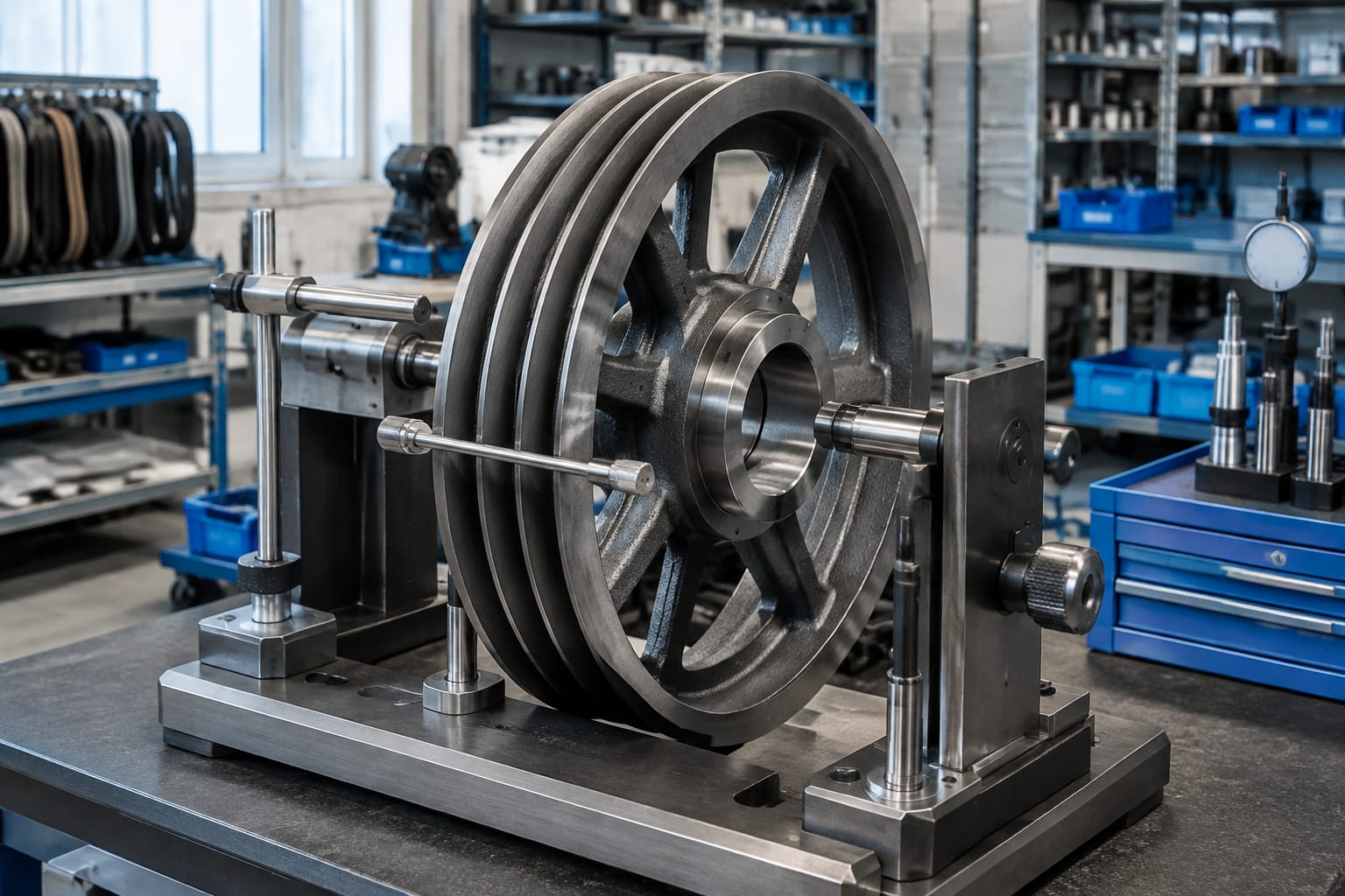
Use calibrated measuring equipment appropriate to the tolerance required. Record:
- Outside diameter: Measure across the outer rim. This identifies the general size but is not sufficient on its own.
- Pitch diameter: Where specified by the manufacturer, this is the effective diameter at which traction occurs. It is especially important because it affects lift speed and rope or belt movement.
- Face width: Measure the usable grooved width, excluding features that do not support the suspension medium.
- Number of grooves or tracks: Count every active rope groove or belt running track.
- Groove pitch: Measure centre-to-centre spacing between adjacent grooves. Use several positions to identify uneven spacing or wear.
- Groove profile: Record groove width, depth, radius, undercut or angle as applicable. A profile gauge or approved template is preferable to visual estimation.
- Groove condition: Note polishing, grooves of unequal depth, chips, corrosion and evidence of rope or belt contact outside the intended surface.
- Hub dimensions: Record hub diameter, length, flange arrangement and offset relative to the groove face.
Shaft and mounting-interface measurements
The shaft interface is a common source of incorrect replacement orders. Confirm:
- Bore diameter and bore length
- Keyway width, depth and position
- Taper, if the sheave uses a tapered bore
- Splines, locking arrangement or clamping features
- Threaded retention details, where applicable
- Hub offset and the sheave’s mounting orientation
- Retaining nut, washer or end-plate arrangement
- Any part numbers cast, stamped or engraved on the component
Do not infer keyway dimensions from the shaft diameter. Two sheaves with the same bore can have different keyway, hub and offset details. Similarly, a sheave with the correct grooves may still be unsuitable if its hub positions the ropes or belts out of line.
A [traction steel pulley for 5500 elevator parts](/products/id-traction-steel-pulley-5500-elevator-parts/) may be relevant to a particular machine family, but the buyer should still submit the machine details, suspension specification and measured interface dimensions for confirmation.
Check machine and suspension compatibility
A practical sourcing decision combines the sheave measurements with the lift’s configuration. The following checklist helps prevent a component that fits physically but performs incorrectly.
| Compatibility area | What to confirm |
|---|---|
| Machine identity | Manufacturer, model, serial number and machine arrangement |
| Suspension medium | Approved rope or belt type, nominal dimensions and part number where available |
| Sheave geometry | Diameter, groove or track count, pitch, profile and face width |
| Shaft interface | Bore, keyway, taper, hub, locking method and mounting orientation |
| Roping arrangement | Number of falls, wrap angle, car and counterweight routing, deflection sheaves |
| Operating conditions | Rated load, speed, duty pattern and any modernisation changes |
| Associated components | Rope or belt condition, deflection sheave alignment, bearings and tension system |
| Documentation | Original parts list, machine drawings and manufacturer service instructions |
The machine serial number is useful, but it should not replace measurement and configuration checks. Equipment can be modernised, re-roped or fitted with different assemblies over its operating life. Conversely, visual similarity between machines is not proof that their sheaves share the same interface or groove specification.
When sourcing for a modernisation, consider whether the new drive, controller, ropes or belts change the traction requirement. A sheave selected for the original installation may not remain correct after alterations to load, speed, roping or suspension technology.
Replacement planning and handling
Plan traction sheave replacement as a controlled maintenance activity. It affects a load-bearing, safety-critical system and should be performed by competent personnel using the equipment manufacturer’s procedures and applicable site safety arrangements.
Before work begins:
- Review the machine documentation and correct replacement specification.
- Inspect ropes or belts, deflection sheaves and tensioning equipment.
- Establish whether the suspension medium must be replaced or adjusted at the same time.
- Confirm lifting points, component mass, access route and suitable lifting equipment.
- Isolate the lift and secure the car and counterweight in accordance with the approved procedure.
- Record the original routing, alignment and hardware position.
- Check the new sheave for transit damage, correct groove count, dimensions and mounting features before installation.
Avoid handling a sheave by dragging it across abrasive surfaces or lifting it through grooves with unsuitable slings. Damage to a new groove surface can affect traction from the first run. Protect the running face from moisture, dust and impact before installation.
A supplier such as Kelevator, which supplies multi-brand elevator spare parts to B2B importers, distributors, maintenance contractors and OEM buyers, can assess an enquiry more effectively when it includes machine identification, clear photos, measured dimensions, groove details and the rope or belt specification. This is more reliable than ordering from a broad visual description.
Inspection after installation
Installation is not complete when the sheave is bolted in place. Inspect the running system during controlled operation and document the baseline condition for future maintenance.
Check the following after installation:
- Verify the sheave is fully seated and retained according to the approved torque and locking procedure.
- Confirm ropes or belts are correctly routed and centred in their grooves or tracks.
- Check alignment with deflection sheaves and adjacent components.
- Set or verify rope tension equalisation using the approved method for the installation.
- Run the lift through normal travel and observe acceleration, deceleration, levelling and noise.
- Inspect for belt edge contact, rope rubbing, unusual vibration or visible movement across grooves.
- Recheck retention, alignment and suspension condition after the prescribed commissioning or bedding-in period.
- Update maintenance records with measurements, replacement details and observations.
Do not compensate for a wrong groove profile by over-tensioning ropes or making unapproved traction adjustments. These actions can conceal the actual problem while increasing wear elsewhere in the system.
FAQ
Can an elevator traction sheave be reused with new ropes?
Sometimes, but only if its groove profile, dimensions and condition remain within the equipment manufacturer’s limits. New ropes installed on worn, polished or uneven grooves may fail to equalise properly and can wear prematurely. Inspect the sheave and ropes as a matched system.
Can a worn traction sheave be repaired?
Re-grooving or other repair may be possible for certain designs, but it is not automatically acceptable. The repair must retain the approved groove geometry, pitch diameter, material integrity and traction characteristics. Obtain the manufacturer’s criteria before authorising the work.
Why are some ropes more worn than others?
Unequal rope tension, inconsistent groove wear, misalignment, different rope stretch, contamination and incorrect installation can all lead to uneven loading. Measuring groove condition and tension across every rope helps identify the cause.
What information should be sent when requesting a replacement?
Provide the machine make, model and serial number; sheave photos; all key dimensions; rope or belt type and size; number of grooves or tracks; shaft bore and keyway details; and any visible markings. Include details of recent modernisation or suspension changes.
A suitable elevator traction sheave is one that matches the complete machine and suspension arrangement, not simply the outside diameter. For relevant steel-belt applications, review the [Otis lift traction steel-belt parts](/products/traction-steel-belt-otis-elevator-parts-lift-parts/) alongside the machine documentation, then confirm the final part selection from measured dimensions and the approved suspension specification.