
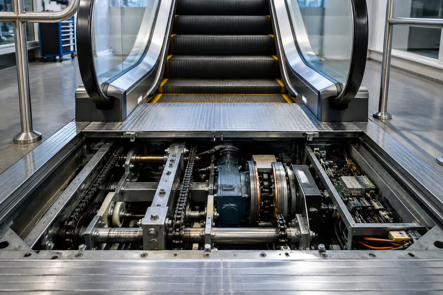
Escalator equipment is the group of mechanical, electrical and safety systems that move passengers safely between levels. Its core components are the step band, drive machine, handrail system, braking equipment, controller and safety circuit. These systems work as one: a worn drive chain, poorly tensioned handrail or incorrectly specified brake part can affect both reliability and passenger safety.
For maintenance teams and buyers, the practical priority is to identify the exact assembly, understand why it has failed, and verify compatibility before ordering a replacement. Part numbers matter, but they should be checked alongside the escalator make, model, installation arrangement and the specifications of the existing component.
Main Escalator Systems at a Glance
An escalator is not simply a moving staircase. It is a coordinated transport machine containing high-load mechanical equipment, electrical controls and protective devices. Most escalator equipment falls into the following systems.
| System | Main purpose | Typical components | Main maintenance concern |
|---|---|---|---|
| Step band | Carries passengers through the escalator | Steps, step chains, axles, rollers, tracks, sprockets | Wear, alignment, chain condition and roller operation |
| Drive system | Provides controlled movement | Motor, gearbox, drive chain or belt, main drive sprocket | Noise, lubrication, heat, vibration and transmission wear |
| Handrail system | Moves handrails in step with passenger travel | Handrail, drive wheel, tension carriage, rollers, guides | Slip, cracking, tracking and tension |
| Braking system | Stops and holds the escalator safely | Main brake, auxiliary brake, coils, brake controller | Brake response, lining condition and electrical operation |
| Control system | Starts, stops and monitors operation | Controller, contactors, inverter where fitted, relays, boards | Fault diagnosis, wiring integrity and correct settings |
| Safety circuit | Detects unsafe conditions and interrupts operation | Emergency stops, comb switches, skirt switches, speed sensors | Switch adjustment, contamination and functional testing |
The exact design differs by manufacturer and generation. A replacement part should therefore be treated as equipment-specific unless its manufacturer documentation confirms interchangeability.
Steps, Chains, Tracks and Comb Plates
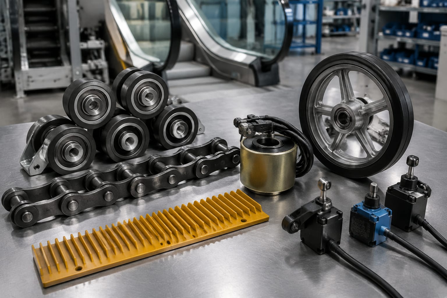
The step band is the visible passenger-carrying system, but much of its critical equipment runs below the landing plates. It includes individual steps connected by step chains, guided by rollers along tracks and driven around upper and lower sprockets.
Steps and step rollers
Escalator steps are designed to mesh correctly with the comb plates at each landing. Step treads, risers, axles and rollers must remain in suitable condition to preserve clearance and smooth movement.
Damaged, bent or heavily worn steps can interfere with the comb plate or adjacent steps. Cracked treads and damaged demarcation inserts can also reduce visibility at the landing. During inspection, check for:
- Step-to-step movement that is uneven, noisy or excessive.
- Loose, damaged or missing tread inserts.
- Cracked castings, worn axle areas or damaged roller housings.
- Steps sitting high, low or out of line relative to neighbouring steps.
- Rubbing marks that indicate contact with skirts, tracks or combs.
Replace a step only with a part that matches the required width, rise, cleat profile, axle configuration and manufacturer-specific fixing arrangement. Similar-looking steps are not necessarily interchangeable.
Step chains, sprockets and tracks
Step chains transfer drive force through the step band. They operate under continual loading, so elongation, poor lubrication, seized rollers and sprocket wear deserve close attention. A chain that has stretched beyond its permitted condition may no longer mesh correctly with the sprockets, increasing noise and accelerating wear.
Track condition is equally important. Step and chain rollers rely on clean, secure tracks with correct geometry. Loose fasteners, worn running surfaces, debris or misalignment can produce vibration and uneven step travel.
Useful inspection points include:
- Chain tension and evidence of unequal tension between left and right chains.
- Roller rotation, wear pattern and secure mounting.
- Sprocket tooth wear and signs of poor chain engagement.
- Lubrication type and application according to the equipment manufacturer's requirements.
- Track fasteners, joints, support brackets and running surfaces.
- Unusual heat, noise or vibration at the drive and return sections.
Do not compensate for a worn chain by making ad hoc tension adjustments. The source of the problem may be chain elongation, a worn sprocket, incorrect alignment or a fault in the tensioning arrangement.
Comb plates and impact protection
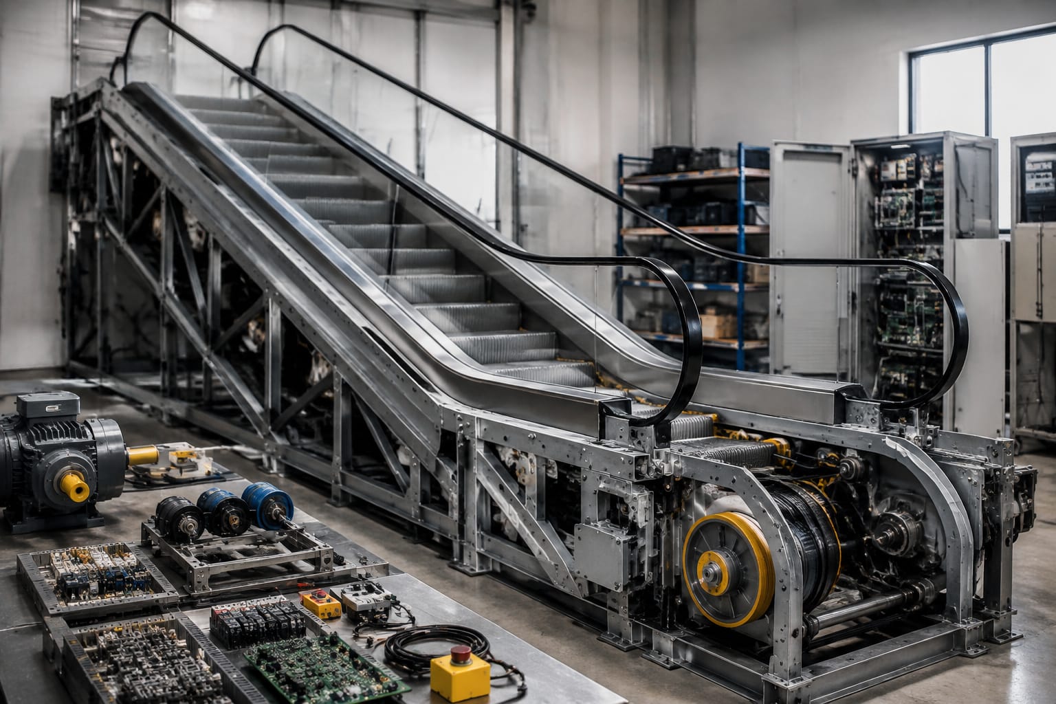
Comb plates create the transition between the moving steps and the fixed landing floor. Their teeth engage with the step cleats and need to be clean, intact and correctly positioned. Broken comb teeth, damaged step cleats and incorrect clearances can create a trapping hazard and may activate the comb impact safety switch.
Inspect comb plates for broken teeth, loose fixings, distorted sections and accumulated debris. Confirm that the impact device or comb switch operates correctly after any work affecting the landing assembly. Replacing only a visibly damaged comb without checking step alignment can leave the original cause unresolved.
Handrail Drive and Tensioning Parts
Handrails should travel smoothly and closely match step speed. They are supported and guided by rollers, driven by one or more handrail drive wheels, and kept under controlled tension by a tension carriage or other manufacturer-specific arrangement.
Handrail issues are often noticed first by passengers: a handrail may lag, surge, slip, run noisily or track towards one side. These symptoms can arise from more than one component, so replacing the handrail alone may not correct the fault.
Common handrail components
A typical handrail system includes:
- The rubber or synthetic handrail belt.
- Handrail inlet guards and entry switches.
- Guide rollers and pressure rollers.
- Drive wheels or friction rollers.
- Tension carriage, springs, weights or adjustment mechanism.
- Lubrication or conditioning equipment where specified by the manufacturer.
- Handrail speed monitoring equipment on applicable units.
Check the handrail surface for splits, glazing, hardening, cuts and contamination. Inspect the drive wheel for wear, embedded debris and degraded friction material. Also examine the tension assembly for seized rollers, damaged springs, misalignment and inadequate travel.
Avoid over-tensioning
A handrail that slips can tempt technicians to increase tension excessively. Over-tensioning can place unnecessary loads on the handrail, drive equipment and guide rollers. It can also conceal a worn drive wheel, contamination or an underlying alignment problem.
Set tension according to the relevant manufacturer procedure. Confirm handrail tracking through the full travel path, not only at the drive section. After adjustment or replacement, verify that the handrail inlet protection and any handrail speed monitoring devices operate as intended.
Main and Auxiliary Brakes
Braking equipment is among the most critical escalator equipment systems. Depending on the design, an escalator may use a main service brake at the drive machine and an auxiliary or additional brake that acts under defined overspeed, unintended movement or drive-train fault conditions.
The terminology and operating arrangement vary by manufacturer. Before selecting brake equipment, establish whether the component is intended as a main brake, auxiliary brake, electromagnetic release coil, brake controller or another related part.
Main brake function
The main brake normally applies when electrical power to the motor is removed or when the control system commands a stop. It is generally spring-applied and electrically released, although the arrangement depends on the machine design.
Maintenance checks should address:
- Brake lining or friction surface condition.
- Air gap, release movement and mechanical clearances.
- Coil condition and electrical connections.
- Evidence of oil, grease or other contamination on friction surfaces.
- Secure mounting, pins, linkages and springs.
- Stopping behaviour under the manufacturer's test procedure.
A brake that does not release fully can cause drag, heat and unnecessary motor load. A brake that does not apply correctly can compromise stopping performance. Neither condition should be managed by unauthorised adjustment or by substituting a component based only on appearance.
Auxiliary and additional brakes
Auxiliary brakes provide another layer of protection where the escalator design requires it. They may operate separately from the main brake and may be linked to speed monitoring, drive-chain monitoring or controller logic.
When a brake controller or related board is identified as defective, confirm the original equipment manufacturer, board number, revision, connector layout, supply requirements and configured application. For relevant Otis applications, review the part identity against the existing unit before sourcing an escalator 508 brake board.
Similarly, an escalator auxiliary brake controller must be assessed against the installed brake system and controller logic. It is not a universal replacement item.
Electromagnetic brake coils should be selected by their precise electrical and mechanical requirements, including the applicable voltage, dimensions, mounting configuration and associated brake assembly. An additional-brake electromagnetic coil may be relevant only where its documented fitment matches the equipment in service.
Motors, Drives and Controllers
The drive machine turns electrical power into controlled escalator movement. It commonly includes an electric motor, gearbox or gearless drive arrangement, transmission components, a drive shaft and the main drive sprocket. The controller manages starting, stopping, direction and safety-circuit monitoring.
Motor and transmission equipment
Motor faults may show as overheating, abnormal noise, poor starting, overload trips or irregular speed. However, these symptoms can also originate in mechanical resistance elsewhere in the escalator. Before condemning a motor, inspect the brake for drag, the drive chain or belt for condition, bearings for noise, gearbox lubricant for signs of degradation and the step band for excessive resistance.
The transmission arrangement may use chains, belts, couplings or gears depending on the escalator. Buyer checks for these components should include:
- Manufacturer and escalator model.
- Part number and revision where available.
- Tooth count, pitch, width and chain or belt profile.
- Bore, keyway, shaft diameter and mounting orientation.
- Material and heat-treatment requirements where specified.
- Whether a matched set is required.
A drive sprocket with worn teeth can reduce the service life of a new chain. Inspect mating components together and replace related worn parts when the maintenance assessment supports it.
Controllers and electrical boards
Escalator controllers vary substantially by manufacturer, model and installation age. A board may have similar connectors to another model yet use different inputs, outputs, firmware, parameter settings or safety logic.
Before replacing a controller, relay, contactor, inverter or printed circuit board, record the fault information and confirm the basic electrical condition. Check supply voltage, protective devices, terminal tightness, wiring damage, contamination, signs of overheating and the status of connected safety switches.
Do not bypass a safety input to keep an escalator running. A bypass can mask the actual defect and defeat a protective function. Fault diagnosis should identify the component or condition causing the safety circuit to open.
Safety Switches and Sensors
Safety switches and sensors monitor areas where passengers, moving equipment or maintenance conditions could create a hazard. When a monitored condition is unsafe, the safety circuit should stop the escalator or prevent it from starting.
Common devices include:
| Device | What it monitors | Typical fault signs |
|---|---|---|
| Emergency stop switch | Manual emergency stop at landings | Damaged cover, poor contact or intermittent circuit |
| Comb impact switch | Comb plate displacement or impact | Escalator stops at landing; damaged comb or misalignment |
| Skirt obstruction switch | Pressure or obstruction at the skirt | Repeated nuisance trips or failure to respond |
| Step-chain monitoring switch | Chain tension, breakage or movement condition | Safety fault, abnormal chain condition or misadjustment |
| Missing-step device | Incorrect step presence or geometry | Stop during travel or after step-band work |
| Handrail inlet switch | Object entrapment at handrail entry | Stops near inlet; damaged guard or switch |
| Speed sensor | Excess speed or speed discrepancy | Overspeed-related fault or no-start condition |
| Brake monitoring switch | Brake application or release position | Brake fault indication or inability to start |
Switches should be inspected for mechanical damage, secure mounting, correct actuator engagement and reliable electrical contacts. Sensor faults can be caused by dirt, moisture, loose brackets, damaged cables or incorrect clearance rather than failure of the sensor itself.
After any adjustment, test the affected safety function according to the equipment manufacturer's procedure and site safety controls. Safety devices should only be serviced by competent personnel working under an appropriate maintenance and isolation process.
Common Wear and Inspection Points
A planned maintenance programme should focus on wear patterns and operating changes before they become shutdowns. The interval and method must follow the manufacturer guidance, site usage, environment and applicable safety requirements, but the following areas regularly warrant attention.
Mechanical inspection checklist
- Step rollers, chain rollers and track surfaces for wear, noise and free movement.
- Step chains and drive chains for lubrication, elongation, tension and sprocket engagement.
- Gearbox, bearings and drive components for leaks, vibration, heat and unusual noise.
- Handrail surface, tracking, tension and drive-wheel condition.
- Comb plates, step cleats and skirt panels for damage, clearances and debris.
- Fasteners, guards and access panels for security and condition.
- Brake linkages, linings, coils and monitoring components for correct operation.
Electrical inspection checklist
- Controller enclosure condition, cleanliness and signs of overheating.
- Terminal connections, earthing and cable insulation.
- Contactors, relays and fuses for condition appropriate to the equipment design.
- Emergency stops and all safety switches for correct operation.
- Sensor brackets, target positions and cable routing.
- Directional operation, starting sequence and controlled stopping behaviour.
Environmental factors in South Africa
Dust, windborne debris, moisture at entrances and heavy foot traffic can increase the maintenance burden on public-facing escalators. Shopping centres, transport facilities and mixed indoor-outdoor entrances may require particular attention to comb areas, step tracks, handrail inlets and controller enclosure cleanliness.
Cleaning should use products and methods suitable for the installed materials. Inappropriate chemicals can damage handrail surfaces, remove specified lubricants or contaminate brake friction surfaces. Keep water and cleaning residue away from electrical compartments and braking equipment.
Sourcing Escalator Replacement Parts
Successful parts sourcing begins with identification, not catalogue matching. Escalator equipment is often manufacturer-specific, and even parts from the same brand can differ across models, revisions and production periods.
Information to collect before requesting a part
Provide as much of the following as possible:
- Escalator manufacturer, model and serial number.
- Existing part number, revision number and clear photographs of labels.
- Photographs showing the part in position, connectors and mounting points.
- Dimensions, electrical ratings and mechanical details where relevant.
- Fault symptoms and any controller fault code.
- Whether the part is for planned maintenance, a confirmed failure or modernisation.
- Quantity required and whether related components have also been inspected.
For mechanical components, dimensions alone may not establish compatibility. For electrical equipment, a matching enclosure or connector is not enough: voltage, contact arrangement, control logic and programmed configuration can be decisive.
Compare new, replacement and modernisation options
A like-for-like replacement is usually appropriate when the installed system remains supported and the original component can be positively identified. Where original equipment is obsolete, a compatible replacement may require engineering confirmation, wiring changes, parameter configuration or associated component upgrades.
Modernisation may be more suitable when faults recur because of ageing controls, unsupported electronics or broader mechanical wear. It should not be assumed that changing a single board, brake component or sensor will resolve a system-level condition.
| Option | Suitable when | Key checks |
|---|---|---|
| Like-for-like replacement | The original part and fitment are confirmed | Part number, revision, dimensions, ratings and mounting |
| Compatible replacement | Documentation supports equivalent use | Functional compatibility, electrical data and installation requirements |
| Repairable component | A competent repair process is available and appropriate | Failure mode, test method, repair scope and follow-up testing |
| Modernisation package | Obsolescence or repeated faults affect wider equipment | Interfaces, safety functions, installation work and lifecycle support |
Common sourcing mistakes
Avoid ordering based on a brief description such as "escalator brake board" or "handrail roller". These descriptions identify a category, not a compatible component. Other common errors include:
- Ignoring a suffix, revision or board version in the original part number.
- Ordering one worn component without checking the mating chain, sprocket, roller or drive surface.
- Replacing a safety switch without investigating why it operated.
- Failing to confirm coil voltage and mounting details.
- Assuming elevator and escalator parts with similar names are interchangeable.
- Installing a part without applying the manufacturer's adjustment and functional test procedure.
Kelevator supplies multi-brand elevator spare parts for B2B importers, distributors, maintenance contractors and OEM buyers. When sourcing escalator-related equipment, submit the installed part identification and application details so the proposed item can be assessed against the required fitment.
FAQ
What is the most important escalator equipment to inspect?
No single component is more important in every situation. Safety devices, brakes, step chains, drive equipment and handrail systems all need planned inspection. A practical approach is to prioritise any condition affecting stopping, step movement, passenger contact points or safety-circuit operation.
How do I know whether an escalator brake part is compatible?
Confirm the original part number and revision, brake assembly type, coil voltage, mounting arrangement, electrical connectors and the escalator manufacturer and model. Where the component interacts with the controller, confirm the control and monitoring requirements as well.
Can a worn handrail be replaced without replacing the drive system?
Often, yes, but the drive wheel, tensioning equipment and guides should be checked at the same time. A new handrail may wear prematurely or slip if the underlying drive or tracking fault remains.
Why does an escalator safety switch keep tripping?
The switch may be correctly responding to a mechanical condition, such as a comb impact, chain movement, obstruction or brake issue. It may also be affected by misalignment, contamination, damaged wiring or a defective actuator. Diagnose the cause before replacing or adjusting the switch.
Accurate identification, inspection of related components and correct commissioning are the basis of dependable escalator equipment maintenance. For a replacement-part enquiry, prepare the equipment details, original part markings and clear installation photographs before comparing available options.
Related product references
For practical catalog examples related to this topic, review [Escalator auxiliary brake controller lift parts elevator accessories](/products/escalator-auxiliary-brake-controller-lift-parts-elevator-accessories/), [Escalator 508 Brake Board OTIS elevator parts lift accessories](/products/escalator-508-brake-board-otis-elevator-parts-lift-accessories/), and [Escalator additional brake electromagnetic coil lift accessories elevator spare parts](/products/escalator-additional-brake-electromagnetic-coil-lift-accessories-elevator-spare-parts/). Confirm the exact model, dimensions, ratings, and connectors before ordering.