
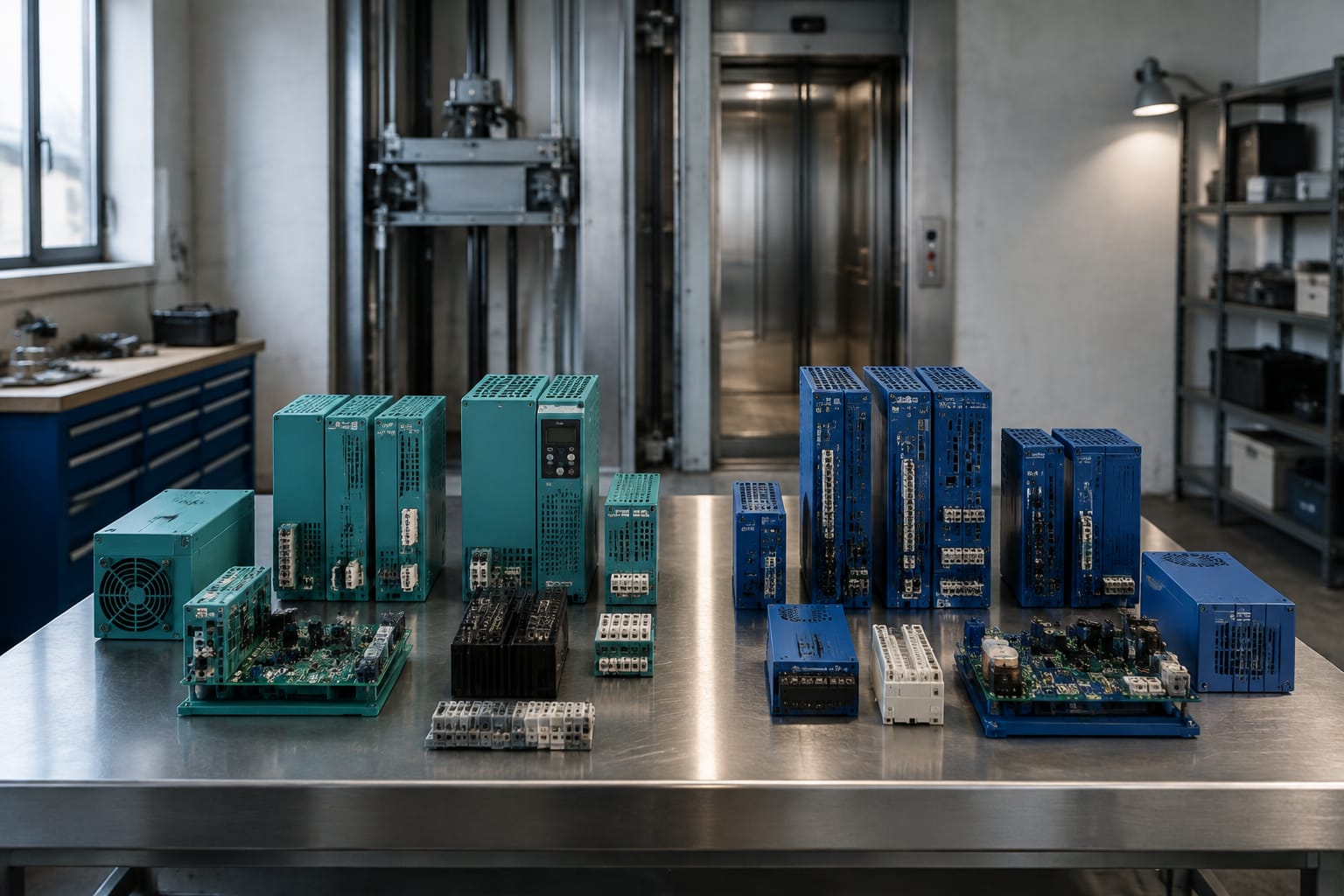
KONE and Sigma lift parts should be sourced as separate product families unless the exact component documentation confirms otherwise. A similar-looking board, a familiar cabinet layout or a matching connector is not enough to establish interchangeability.
The safest approach is to identify the lift and controller first, then match the failed component by its full label, part code, hardware revision, electrical requirements and communication role. This reduces repeat faults, avoids installation delays and gives a supplier enough information to quote the correct item.
KONE and Sigma are distinct product families
“KONE Sigma” is often used as a broad search phrase, but it should not be treated as a universal compatibility category. KONE-branded and Sigma-branded equipment may use different controller architectures, board naming conventions, software configurations, connectors and signalling arrangements.
For a maintenance contractor or sourcing team, the practical consequence is simple: do not substitute a KONE part for a Sigma part, or the reverse, based only on appearance or a partial description such as “door board”, “car board” or “drive PCB”.
A board performs a job within a particular system. Two boards may both manage car communication, input/output signals or power distribution, yet still be incompatible because they differ in one or more of the following areas:
- Controller family and cabinet generation
- Board hardware revision
- Firmware or parameter set
- Supply voltage and current requirements
- Connector type, pin allocation and cable arrangement
- Serial communication protocol
- Safety circuit integration
- Drive or door-operator interface
Treat the original part number as the starting point. Where this is missing or unreadable, collect more evidence before ordering: controller photographs, wiring references, board label images, lift model information and the fault history.
This matters particularly for imported equipment in South Africa. A site may have undergone partial modernisation, received a replacement controller or had components fitted during earlier repairs. The lift brand on the landing entrance or car operating panel may not accurately identify the controller or the board fitted in the cabinet today.
Identify the elevator before the component
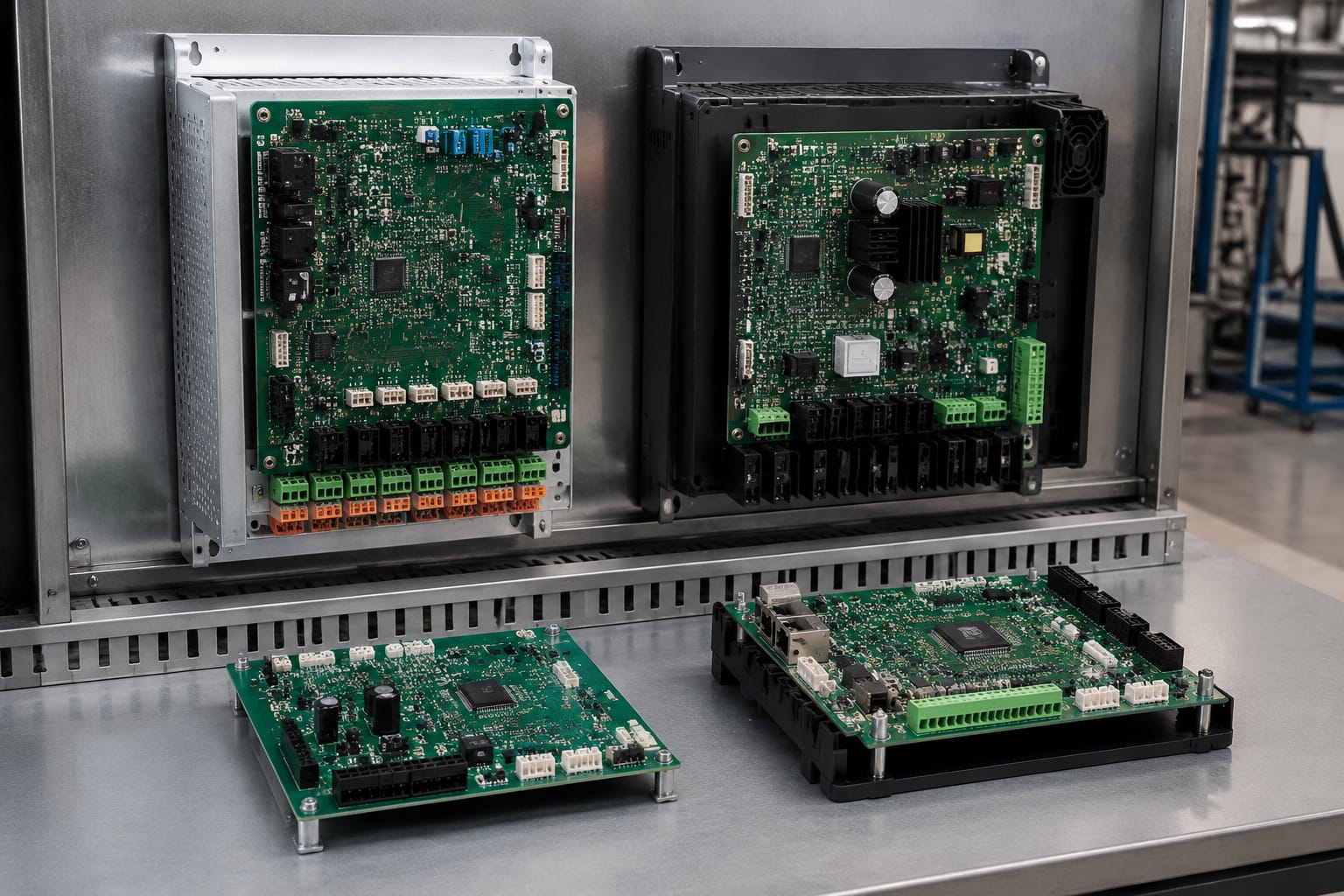
Start with the lift installation, not the failed board. Confirming the equipment identity prevents a common sourcing mistake: ordering a component that matches the visible PCB but belongs to a different controller system.
Record the information from the controller cabinet, machine-room documentation where present, and the component itself. The most useful details are usually available on identification plates, board labels and cabinet wiring diagrams.
Build an equipment identification record
Before requesting a quotation or comparing alternatives, capture:
- Lift manufacturer or system brand shown on the controller identification plate
- Controller model, type and serial number
- Installation or modernisation reference, where available
- Number of cars and floors served
- Door operator make and model
- Main supply details shown on the cabinet
- Type of drive system and drive label
- Board position in the cabinet or car-top box
- Full failed-board part number, including suffixes
- Hardware revision, issue number and manufacturing code
- LED condition, fault code or observed symptom
- Clear photographs of both sides of the board and all connectors
Use the controller plate as the primary reference, not just the lift car branding. A replacement car fixture or a modernised door system may create misleading visual clues.
Separate the symptom from the part diagnosis
A fault symptom does not necessarily prove which board has failed. For example, intermittent car communication can result from a communication board, loose travelling-cable connections, power instability, damaged terminations, incorrect addressing or a controller fault. Likewise, a drive fault may originate in the drive itself, its control interface, incoming supply or external safety-chain conditions.
Before treating a board as defective, check the basic causes allowed by the site’s maintenance procedures:
- Record fault codes and the operating conditions when the fault occurs.
- Inspect connectors for incomplete insertion, corrosion, heat damage or bent pins.
- Check relevant supply voltages against the equipment documentation.
- Confirm cable continuity and screening where the circuit design requires it.
- Compare LEDs, switches, jumper settings and addresses with the existing records.
- Only remove or replace components using qualified personnel and the manufacturer’s safety procedures.
This diagnostic discipline is especially important when a high-value control, drive or communication board is involved. A correctly identified part cannot solve a fault caused elsewhere in the system.
Compare board names and functions
Board names can be useful, but they are not a sufficient basis for ordering. Names may be abbreviated, local to a controller family or used differently between generations. Instead, compare the board’s actual system function together with its exact identification data.
The table below shows the distinction a buyer should make when assessing common board categories.
| Board category | Typical role | What must be matched | Common sourcing mistake |
|---|---|---|---|
| Main controller board | Coordinates lift operation and safety-related inputs within the controller design | Controller family, part code, revision, software requirements, I/O arrangement | Ordering by cabinet appearance alone |
| Car communication board | Exchanges signals between car equipment and controller | Bus type, addressing, connector pinout, cable interface, system generation | Assuming all car bus boards use the same protocol |
| Drive interface or drive board | Connects lift control functions to the motor drive or drive system | Drive model, interface type, voltage, parameter requirements and revision | Matching only the drive brand |
| Power board | Distributes or regulates supply to designated circuits | Input/output voltages, current capacity, fuse arrangement, connector layout | Replacing with a visually similar power PCB |
| Door interface board | Interfaces door equipment with the lift control system | Door operator model, controller interface, supply and safety inputs | Treating all door boards as door-operator interchangeable |
| I/O expansion board | Adds monitored inputs and controlled outputs | Input type, output rating, board address, bus protocol and controller support | Ignoring configuration or addressing |
When comparing two listings, ask a functional question: “Does this exact board operate in the same controller, in the same position, with the same electrical and communications interface?” A product description that says only “suitable for Sigma” or “KONE compatible” should be supported by a specific part number and application confirmation.
For Sigma systems, a Sigma elevator driver board should be evaluated against the drive and controller interface details, not selected merely because it is described as a driver board. The same principle applies to every control PCB in the installation.
Record labels, codes and revisions
The full label is the most valuable sourcing document. Do not omit prefixes, suffixes, dashes, spaces or revision identifiers when submitting an enquiry. Small differences can identify a different hardware version, voltage variant, production update or equipment family.
What to photograph and transcribe
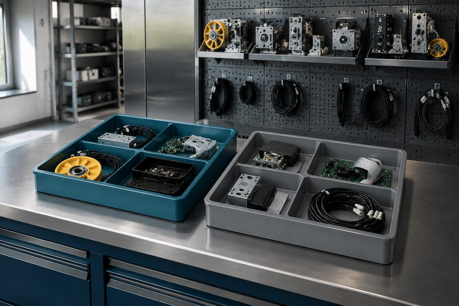
Take a straight, well-lit photograph of each label before unplugging the board. Capture both the fitted position and the board itself. Then transcribe the information into the purchase request so it remains searchable even if an image is unclear.
Look for:
- Manufacturer name or logo
- Exact part number
- PCB number or assembly number
- Hardware revision, version, issue or “Rev” marking
- Barcode and serial number
- Date code or production batch code
- Voltage markings
- Connector identifiers
- Fuse ratings and ratings labels
- Firmware chip labels where visible and relevant
- Handwritten settings or site labels, which should be recorded separately from factory identifiers
Avoid collapsing different numbers into one generic reference. A PCB fabrication number, an assembly code and a supplier stock code can all appear on one board, but they do not always identify the same purchasable item. The label that corresponds to the installed assembly is generally the key reference.
Revision control is a compatibility control
Revision matching is not administrative detail. Later revisions may correct design issues or support additional functions, but they can also require changed firmware, different harnesses or a compatible controller version. Earlier boards may be obsolete even where the connector layout looks unchanged.
Where the offered revision differs from the removed board, obtain confirmation of the intended replacement relationship from reliable technical documentation or a supplier able to assess the full equipment information. Do not assume “newer” automatically means “plug-and-play”.
For critical components, retain a record of the removed part, the fitted replacement, the date, the installer and any configuration changes. This makes the next repair faster and helps distinguish recurring equipment faults from an isolated board failure.
Check voltage, connectors and protocols
An exact-looking part can still fail to operate, or be damaged, if its electrical or communication requirements do not match the installation. Verify the board against the lift’s documentation and the cabinet wiring before it is ordered or installed.
Electrical checks
Confirm the following values from the board label, circuit diagram and controller documentation:
- Nominal supply voltage and whether it is AC or DC
- Permitted supply range, where stated
- Current demand and protection requirements
- Input and output voltage levels
- Relay contact ratings, where relevant
- Earthing and screening requirements
- Fuse type and rating
- Power connector position and pin allocation
Do not rely on wire colour alone. Cabling can be altered during repairs, and colour conventions vary between installations. Use terminal markers, drawings and measured values taken by competent personnel.
Connector checks
A connector that physically mates may have a different pinout. Compare:
- Connector family and number of pins
- Keying, latch orientation and gender
- Pin numbers and signal assignments
- Cable orientation and routing
- Presence of jumpers, termination resistors or address switches
- Associated harness part numbers, if marked
Photograph connectors with their reference designators visible. A wide cabinet photograph is helpful, but a close image showing labels such as CN1, J4 or X12 is more useful for precise comparison.
Protocol and configuration checks
Communication boards require an additional level of care. The board must communicate in the expected language, at the expected speed and addressing arrangement, with the controller and peripheral equipment.
Confirm, where documentation identifies them:
- Communication bus or interface type
- Board address or car address
- Termination arrangement
- Firmware dependency
- Controller software compatibility
- Configuration switches and jumper positions
- Whether commissioning tools or parameter loading are required
Never move jumpers, alter firmware or copy settings from another lift simply to make a board fit. Configuration can affect operation beyond the immediate fault and may have safety implications. Follow the applicable equipment documentation and site procedures.
Source Sigma drive and communication boards
Sigma drive and communication boards should be sourced with a clear picture of the controller, connected equipment and exact replacement reference. These boards are often central to system operation, so vague descriptions create a higher risk of incorrect ordering.
For a drive-related request, provide the drive label as well as the board label. Include the motor-drive model, supply details, fault indication, controller model and the board’s connection point. A board fitted near a drive may be an interface, power, feedback or control component; its location alone does not establish its function.
For car communication faults, distinguish between a board installed in the main controller, car-top box, car operating panel or other field enclosure. Identify the cables connected to it and whether the board is addressed for a particular car. This prevents a multi-car or group-system part being confused with a single-car equivalent.
A Sigma car communication board is relevant when the installed unit’s exact board information and communication role have been established. Compare the listed component against the removed unit’s label, revision, connector arrangement and controller application before treating it as a replacement.
Power boards deserve the same level of scrutiny. A Sigma lift power board must be matched to the required supply and output functions. Its physical size, terminal count or fuse locations do not prove it has the correct electrical characteristics.
When sourcing any Sigma board, send a concise technical pack rather than a single photograph. A useful pack contains:
- Controller plate image
- Front and rear board images
- Close-up images of labels and connectors
- Cabinet location of the board
- Relevant wiring diagram page, if available
- Fault description and codes
- Any prior replacement history
- Required quantity and whether the request is for repair stock or an active breakdown
This information allows a meaningful compatibility assessment and reduces time lost clarifying basic details after the order process has started.
Source KONE-specific components
KONE-specific components should be identified by the exact controller or subsystem they serve. KONE installations can vary by controller generation and modernisation history, so a KONE-branded label alone is not a complete specification.
Start by separating the component into its operating area:
- Main controller and I/O system
- Car communication and car fixtures
- Landing equipment
- Door equipment
- Motor drive or drive interface
- Positioning and shaft equipment
- Power supply and cabinet hardware
Then match the item against the controller documentation and the removed component’s complete reference. For electronics, check the board revision, connector arrangement and any configured settings. For mechanical or door components, confirm dimensions, handedness, mounting pattern and the associated operator model in addition to the printed code.
Do not use a Sigma reference to infer a KONE equivalent, even if a reseller groups them in a broad category. A functional description may assist a search, but it should lead back to a verified KONE part number or documented replacement relationship.
For KONE parts where the original number is unavailable, the next-best evidence is usually the controller type, cabinet photograph, wiring diagram reference and close images of surrounding boards. This can narrow the possible family, but it remains less reliable than an intact label.
A supplier should be able to work from the technical evidence supplied. Kelevator supplies multi-brand lift spare parts to B2B importers, distributors, maintenance contractors and OEM buyers, so a structured identification record is more useful than a broad request for a “KONE Sigma board”.
Final compatibility checklist
Use this checklist before approving an order or fitting a replacement KONE or Sigma component.
- [ ] The lift controller manufacturer, model and serial or site reference have been recorded.
- [ ] The failed component’s complete part number has been captured from its label.
- [ ] Hardware revision, version and relevant manufacturing codes have been compared.
- [ ] The offered part is confirmed for the correct KONE or Sigma controller family.
- [ ] The board’s function and cabinet or car position match the original.
- [ ] Supply voltage, current requirements and AC/DC type have been checked.
- [ ] Connector type, pin count, keying and pinout have been compared.
- [ ] Communication protocol, addressing, termination and configuration requirements have been checked where applicable.
- [ ] Connected equipment, such as the drive, door operator or car bus, has been identified.
- [ ] Any required firmware, parameters, commissioning steps or authorised configuration work have been confirmed.
- [ ] The fault diagnosis has considered cables, power supply, connections and external inputs rather than assuming the board is defective.
- [ ] The replacement is installed and tested by appropriately qualified personnel under the equipment manufacturer’s procedures.
The central rule is straightforward: source by verified system identity and full component data, not by brand name or visual similarity. Assemble the controller details, board labels, revision information and photographs before placing a request; that gives your technical team or parts supplier the basis needed to assess the correct KONE or Sigma replacement.
Related product references
For practical catalog examples related to this topic, review [Elevator Driver Board SIGMA elevator parts lift accessories](/products/elevator-driver-board-sigma-elevator-parts-lift-accessories/), [Car communication board SIGMA elevator parts](/products/car-communication-board-sigma-elevator-parts/), and [Power Board SIGMA elevator parts lift accessories](/products/power-board-sigma-elevator-parts-lift-accessories-2/). Confirm the exact model, dimensions, ratings, and connectors before ordering.