
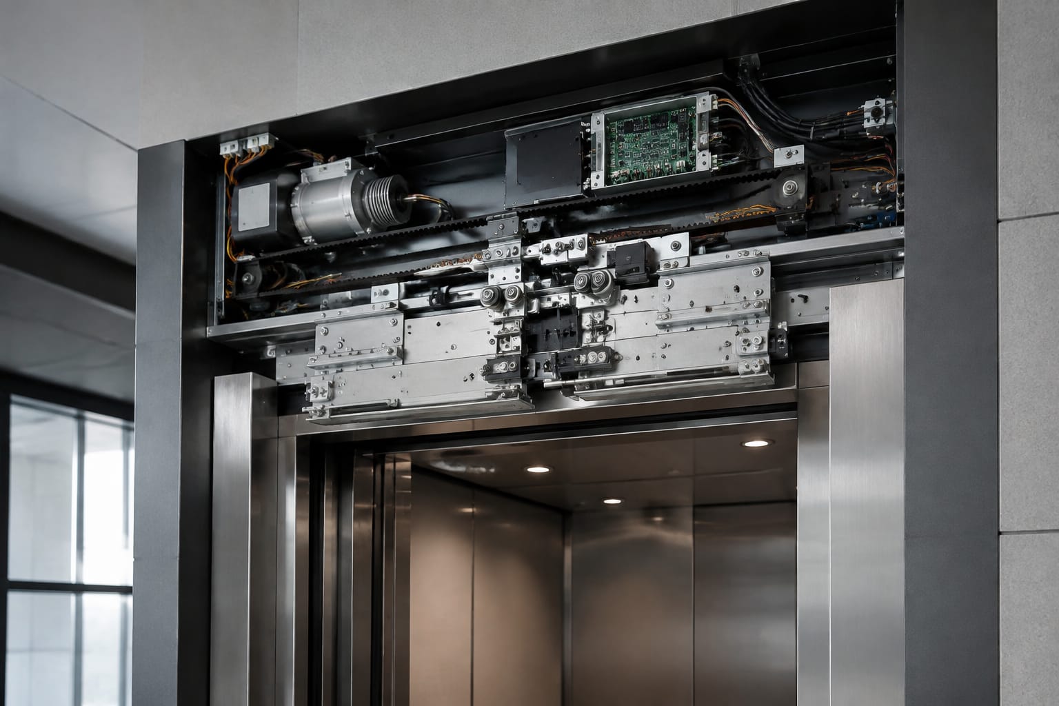
A KONE elevator door is a coordinated safety system, not a collection of interchangeable components. A correct replacement starts by identifying the door-operator model and checking the failed part against the original assembly, electrical rating, connector arrangement, software or revision marking, and mechanical mounting points.
For maintenance contractors and sourcing teams, the most reliable approach is to diagnose the fault first, then match the replacement to the actual landing-door and car-door equipment in service. A motor, lock contact or controller that looks similar may still be incompatible with the operator, door panel weight, wiring loom or safety circuit.
How the KONE door system works
An elevator has two related door systems:
- The car door travels with the lift car and is driven by a door operator mounted on or near the car entrance.
- The landing door remains at each floor and is normally locked closed. It opens only when the car door engages it correctly at a landing.
The car-door operator receives commands from the lift controller and uses a motor, transmission arrangement and door mechanism to open and close the panels. The operator monitors door position and, depending on the equipment fitted, may use sensors or an encoder to manage speed, direction and obstruction response.
When the car reaches a landing, the car-door knife engages the landing-door lock mechanism. This releases the landing door so both doors can move together. As the doors close, the landing lock must return to its secure position and its safety contacts must prove that the landing door is locked before the lift can travel.
This sequence means one apparent door fault can originate elsewhere. A car door that fails to close may be caused by friction in the sill, a weak motor drive, an incorrectly adjusted lock, a damaged knife, a failed safety contact or a controller input that does not recognise the closed condition.
Door locks and safety contacts
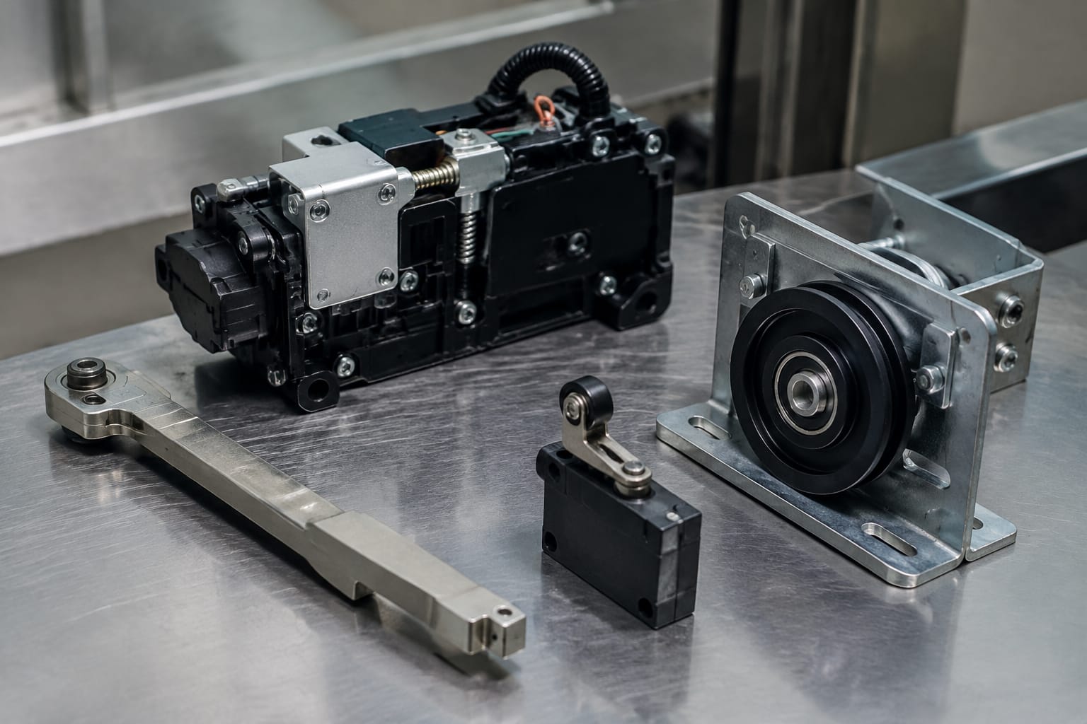
Landing-door locks are safety-critical components. Their role is to prevent a landing door from being opened when the lift car is not present and to confirm that the door has locked before normal travel is permitted.
A typical lock assembly includes a mechanical locking element and one or more electrical contacts. The exact form varies by door type and generation, but the selection principle is consistent: the replacement must match the original lock function and physical arrangement, not merely the general appearance.
What to check on a replacement lock
Before ordering a KONE elevator door lock or compatible part, record:
- The part number and all suffixes on the lock body or label.
- The landing-door type and the number of panels.
- Left- or right-hand orientation, where applicable.
- Lock body mounting-hole positions and dimensions.
- The hook, roller, cam or release arrangement.
- Contact count, terminal style and wiring configuration.
- The original contact function: normally open, normally closed or a combined arrangement.
- The supplied voltage or circuit requirements where marked.
- Any revision or manufacturing code.
A lock contact cannot be selected only by terminal count. Two contacts may have the same connector style but different switching behaviour, which can leave the safety chain open or cause incorrect status reporting.
For lock-related maintenance items, compare the existing device closely with relevant [KONE-compatible door lock, wheel and switch parts](/products/amd-door-lock-wheel-switch-door-bracket-kone-elevator-parts-lift-accessories/). Confirm the item’s drawings, dimensions and technical data against the equipment on site before committing to a replacement.
Frequent lock-related symptoms
| Symptom | Possible cause | Check before replacing |
|---|---|---|
| Lift will not leave a floor | Landing lock contact not proving closed | Door closure, contact actuation, wiring continuity and controller fault record |
| Landing door can be moved excessively | Worn lock parts or incorrect adjustment | Mechanical engagement, fasteners, door-panel alignment and rollers |
| Doors reopen near the end of closing | Lock or door mechanism binding | Sill cleanliness, panel movement, knife clearance and lock release path |
| Intermittent door-zone or safety-chain fault | Loose contact, damaged cable or inconsistent lock operation | Terminals, loom movement, contact repeatability and door alignment |
| Landing door will not release with the car present | Knife does not engage lock correctly | Knife position, car levelling, lock linkage and mechanical damage |
Never bypass, bridge or permanently defeat a landing-door safety contact to return a lift to service. It may conceal the actual fault and creates an unacceptable safety risk.
Door knives and mechanical linkages
The door knife is the mechanical interface between the car door and landing door. At the landing, it engages the release portion of the landing lock, permitting the car and landing doors to open together. It must be correctly positioned in relation to the lock and remain secure through repeated operation.
Door knives, vanes, rollers, brackets, couplings and linkages are often overlooked because they are mechanical parts. Yet wear in these areas can create symptoms that resemble an electrical failure: irregular opening, a noisy release, inconsistent unlocking or repeated door reversals.
Mechanical checks that matter
Inspect the following with the door equipment safely isolated and in accordance with the site’s maintenance procedures:
- Knife mounting bolts, bracket condition and visible distortion.
- Knife alignment at landing level.
- Clearance between the knife and the lock during approach and operation.
- Wear on rollers, pivots and linkage joints.
- Door-panel hangers and roller movement.
- Sill grooves for dirt, debris or damaged guides.
- Door coupling operation between car and landing panels.
- Signs of impact damage on door edges, hangers or lock components.
An incorrectly adjusted knife can either fail to release the lock or exert excessive force on it. Replacing only the lock in this situation may produce another early failure. Similarly, a worn roller can cause a door to drag, raising the load seen by the motor and controller.
Where the knife itself or its locking interface is damaged, select a [car-door knife and door lock device](/products/car-door-knife-door-lock-device-kone-elevator-parts-lift-accessories/) only after matching its profile, fixing arrangement and applicable door system. A visually similar knife can have different travel, release geometry or mounting centres.
Common mechanical mistakes
Do not assume a noisy door operator needs a motor. First rule out dirty sills, rubbing panels, seized rollers, bent linkages and a landing lock that is not releasing cleanly. These faults increase resistance and can cause a functioning motor to stall or a controller to report a door movement error.
Avoid adjusting locks or knives solely to make a fault disappear. Adjustment should restore the specified mechanical relationship, not compensate for worn components, a damaged panel or poor landing alignment.
Door motors and controllers
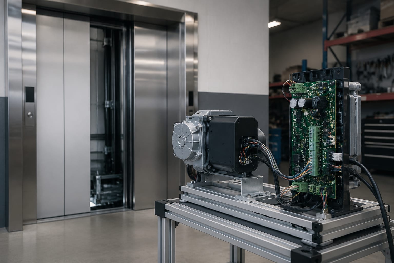
The door motor supplies movement; the door controller manages it. Depending on the KONE door-operator generation, the motor may be driven through a belt, gear, arm or other transmission system, while the controller evaluates position and movement feedback.
Motor and controller compatibility is especially important because their electrical and software requirements can differ even within similar-looking door operators. A replacement motor must suit the correct drive system, feedback method and mechanical load. A controller must suit the operator hardware, associated motor and lift interface.
Motor selection criteria
When matching a door motor, confirm:
- Complete original motor part number and revision.
- Rated voltage and current, as marked.
- AC, DC or other motor type.
- Power rating, speed and feedback provision where stated.
- Shaft diameter, length, keyway, gear or pulley arrangement.
- Motor mounting pattern and physical envelope.
- Cable length, plug type and pin configuration.
- Brake arrangement, if fitted.
- Door-operator model and the door configuration it serves.
Motor ratings are not optional details. A motor with the wrong voltage or feedback arrangement may fail to operate correctly or may damage the controller. A different shaft or pulley can also alter opening speed, closing force and terminal positions.
Controller selection criteria
A door controller should be identified from its own label and from the operator it controls. Record:
- Controller part number and hardware revision.
- Firmware or software identification if available.
- Input and output connector references.
- Motor connector and feedback connector types.
- Supply requirements.
- Operator model and wiring diagram reference.
- Fault codes or diagnostic indications before removal.
- Any associated sensors, encoder or limit-switch arrangement.
A controller is not necessarily the cause when the door refuses to move. The controller may be correctly responding to an open safety circuit, blocked door movement, missing position feedback or a supply issue. Replacing it without testing the inputs and mechanical condition can add cost without resolving the root fault.
For a focused comparison of motor and electronic control items, review the available [KONE door motor and controller parts](/products/kone-elevator-parts-door-motor-controller/) alongside the identification data collected from the installation. Product compatibility must still be confirmed against the original unit.
Identify the door-operator model
The door-operator model is the starting point for a reliable parts match. The operator assembly may carry a plate, label or stamped identifier, commonly located on the car-top door operator, controller enclosure, motor or operator beam.
Do not rely on the lift brand shown in the car or on the landing-door appearance. A building may have undergone modernisation, partial door replacement or controller upgrades. The lift could therefore contain door equipment from a different generation or a mixed configuration.
Build an identification record
A useful site record includes clear photographs and the following details:
- Door-operator model and serial or identification number.
- Part number and revision from the failed component.
- Wide photographs showing the component in its installed position.
- Close photographs of all connectors, terminals and labels.
- Door opening type, panel count and approximate clear opening.
- Motor shaft, pulley or gearbox details where the motor is involved.
- Lock handing, mounting arrangement and contact configuration where the lock is involved.
- The controller’s LEDs, display or recorded fault code where fitted.
- A concise description of when the fault occurs: opening, closing, levelling, lock release or travel permission.
- Details of previous repairs or recently replaced parts.
Photographs should show the label clearly enough to read. Include a scale or measure key distances where no formal drawing is available. This is more useful than a distant photo of the entire landing.
Match ratings, connectors and revisions
Correct identification has two layers: establish whether a part is mechanically suitable, then confirm whether it is electrically and functionally compatible. Both are necessary.
Compatibility checklist
| Area | What to match | Why it matters |
|---|---|---|
| Mechanical fit | Mounting centres, handedness, shaft profile, pulley, linkage and clearances | Prevents installation problems and incorrect door movement |
| Electrical supply | Voltage, current, phase or supply type | Reduces risk of non-operation or equipment damage |
| Feedback | Encoder, sensor, limit switch and signal arrangement | Allows the controller to track door position correctly |
| Connectors | Plug housing, keying, pin count, pinout and cable length | Prevents incorrect or incomplete wiring connections |
| Control interface | Inputs, outputs and safety-chain function | Ensures the part communicates correctly with the operator and lift system |
| Revision | Hardware, firmware and replacement-part revision | Addresses changes between production versions |
| Application | Operator model, panel arrangement and duty requirements | Confirms the item suits the actual installation |
Part-number prefixes, suffixes and revision marks can be significant. Do not drop suffixes when requesting a quote or searching a catalogue. They may indicate a changed connector, updated electronic board, alternative mounting or a superseded design.
Where an original item has been superseded, confirm whether the replacement requires an adaptor, altered wiring, parameter change, firmware update or accompanying components. A superseded part is not automatically a direct plug-in replacement.
For imported parts, verify the electrical rating and documentation against the site equipment before installation. Local supply conditions and the installed controller arrangement must be suitable for the exact item, regardless of where the part was sourced.
Diagnose before replacing a part
A disciplined diagnosis reduces repeat visits and prevents unnecessary replacement of expensive door equipment. Start with the simplest conditions and work towards the electronic components.
A practical fault-finding order
- Read the fault information. Record lift controller and door controller codes before cycling power or disconnecting equipment.
- Observe the door cycle. Note whether the issue occurs while opening, closing, unlocking, locking or handing travel permission back to the lift controller.
- Check physical resistance. With the correct safety controls in place, inspect for debris, damaged sill tracks, rubbing panels, worn rollers and binding linkages.
- Inspect lock and knife operation. Confirm that the knife engages correctly and that the lock releases and re-locks consistently.
- Check safety contacts and wiring. Test continuity and actuation at the affected landing; inspect flexing cables and terminal connections.
- Verify the motor circuit. Check connector seating, cable condition and relevant electrical values against the equipment documentation.
- Assess position feedback. Inspect encoder, sensor or limit-switch condition and wiring where used.
- Evaluate the controller last. Only after inputs, supply, motor condition and mechanical movement have been assessed should the controller become the leading suspect.
This order is deliberately practical. A door controller cannot make a mechanically jammed door run normally, and a new motor will not correct a broken lock contact.
Symptoms that need broader investigation
A fault at one landing may point to that landing’s lock, door panel or local wiring. A fault occurring at every landing is more likely to involve the car-door operator, travelling cable, controller, power supply or shared car-door mechanism. This is a useful diagnostic distinction, but it is not conclusive on its own.
Intermittent faults need particular care. Record the floor, direction of travel, door position, temperature conditions if relevant, and any related fault code. A loose plug or cable that fails only as the door moves can be missed by a static visual check.
Commission and test the repaired door
Part replacement is only one stage of the repair. The door must be commissioned and tested by competent personnel using the applicable site procedures and safety requirements.
Before restoring normal operation, check that all guards, covers, fasteners and cable restraints have been refitted. Ensure that the door panels move smoothly without rubbing, the knife and landing lock engage correctly, and no tool or loose material remains in the equipment area.
Post-repair commissioning checks
Perform the checks appropriate to the installation and the work completed:
- Confirm correct movement direction and stable opening and closing operation.
- Check opening and closing positions at each affected landing.
- Verify smooth lock release and secure re-locking.
- Confirm safety contact operation and travel permission only when the landing doors are correctly locked.
- Test obstruction or protective-edge functions where fitted and applicable.
- Review door-controller indications and clear only faults that have been resolved.
- Check repeated cycles rather than relying on a single successful run.
- Reinspect fixings, connectors and cable routing after cycling.
- Record the part fitted, revision, fault condition and test outcome in the maintenance record.
Do not increase door force, alter timing or bypass protective functions merely to achieve a passing cycle. Where parameter changes are required after fitting a compatible controller or motor, use the correct technical information and ensure the settings suit the installed door operator.
FAQ
Can any KONE door lock be used if the mounting holes match?
No. The mechanical fit is only one requirement. The lock’s release geometry, handing, safety contact arrangement and electrical function must also match the existing system.
Is a KONE door motor interchangeable with another motor of the same voltage?
Not necessarily. Shaft dimensions, pulley or gear arrangement, speed, feedback device, connector pinout and controller compatibility can all differ. Match the complete motor identification and operator application.
Should the door controller be replaced when a door fault code appears?
Not automatically. A fault code can be caused by a safety input, mechanical resistance, motor wiring, feedback issue or power problem. Diagnose the supporting conditions before replacing the controller.
What information should be sent when sourcing a replacement part?
Provide the original part number with all suffixes, the door-operator model, clear label and connector photographs, the installation position, the fault description and any fault code. For locks and knives, include handing and mounting dimensions.
For multi-brand sourcing requirements, Kelevator can help B2B importers, distributors, maintenance contractors and OEM buyers compare identified elevator spare parts. Start with the operator and component identification record so the required compatibility can be assessed accurately.