
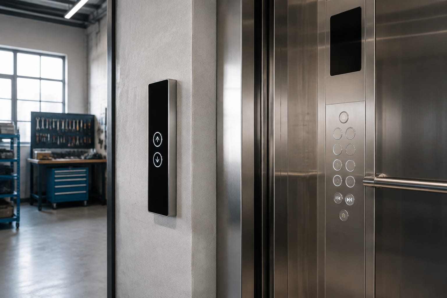
Replacing Schindler buttons successfully depends on identifying the complete button assembly and its application, not merely matching the visible cap. Record whether the button is on the car operating panel (COP) or landing operating panel (LOP), then confirm the lift family, board code, dimensions, illumination, symbol, mounting method and connector before ordering.
For Schindler buttons used on 3300 and 3600 installations, a visually similar part can still be incompatible if its touch board, pin layout or mounting points differ. Photographing the front and back of the removed assembly, together with the panel and any labels, gives a far more reliable basis for selection.
Schindler COP and LOP button functions
A Schindler COP button is installed inside the lift car. It allows passengers to choose a floor and may include door open, door close, alarm, fan, emergency or other car-control functions. A LOP button is fitted at a landing and is generally used to call the lift up or down.
The function affects what must be matched during replacement. A floor-selection button in the COP may use a different symbol, legend arrangement, illumination state or electronic interface from a hall-call button, even where the front appearance is alike.
| Feature to check | COP button | LOP button |
|---|---|---|
| Location | Inside the lift car | At a floor landing |
| Main purpose | Select floor or car function | Call lift in an available direction |
| Typical symbols | Floor number, door, alarm or service icon | Up, down or combined direction symbol |
| Common replacement concern | Floor identification and car panel compatibility | Direction indication and landing board compatibility |
| Wiring or connection | May connect through a car-panel board or harness | Often connects to a hall-call board or display board |
Before removing a failed unit, identify its exact position. For example, “Level 3 COP button” is more useful than “round Schindler button”, while “ground-floor down LOP call button” provides the context needed to check the symbol and application.
Do not assume that every button in one building is identical. Mixed panels, phased modernisations and replacements made during previous maintenance work can result in different assemblies being fitted to otherwise similar lifts.
Identify 3300 and 3600 applications
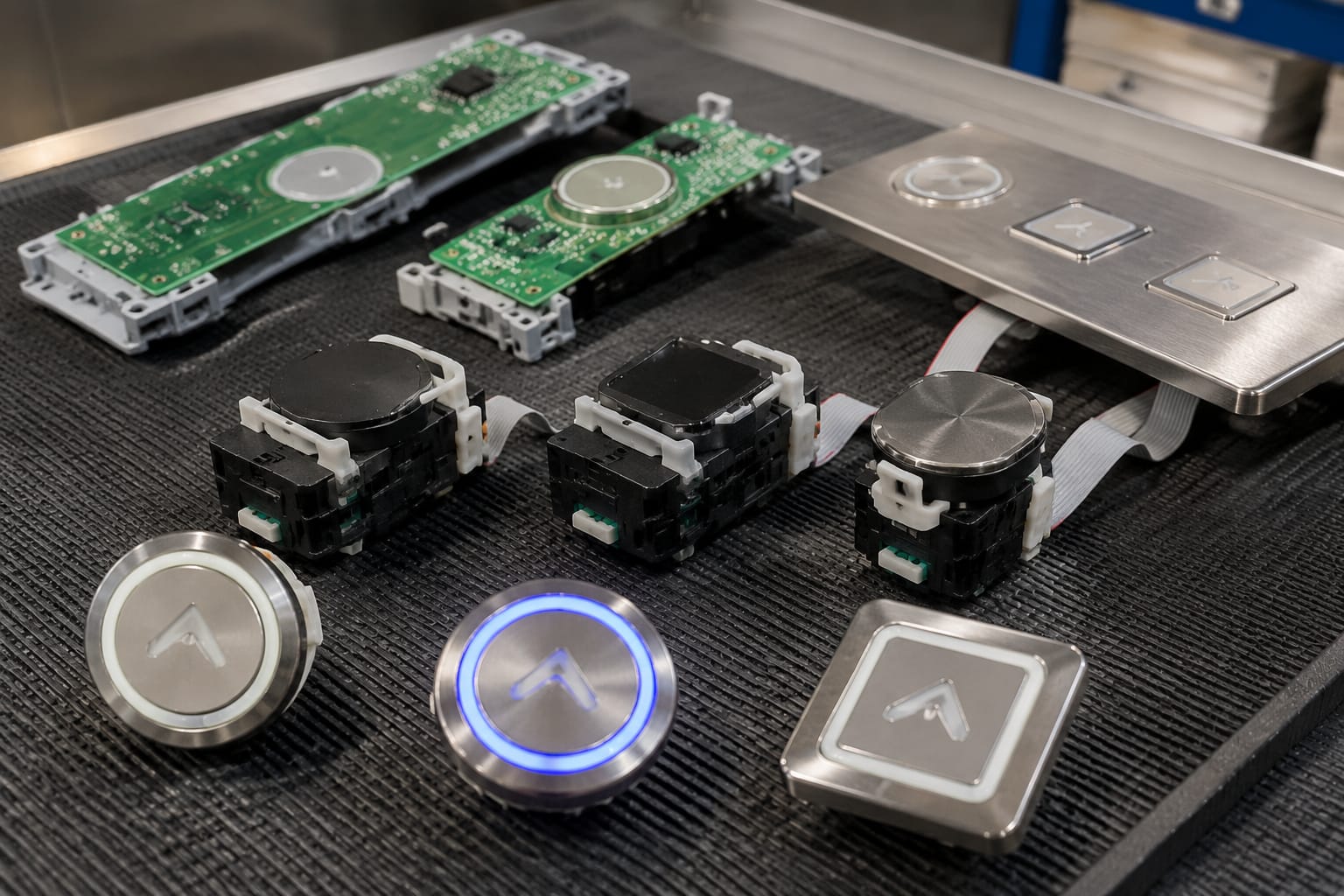
Schindler 3300 and 3600 references are important starting points, but they do not by themselves establish a complete part match. Button boards, display boards and panel configurations can vary by installation, panel revision and the function assigned to the position.
Start by recording all available identifiers:
- Lift model or controller family stated on the installation documentation or equipment labels.
- Whether the button is fitted to a 3300 or 3600 car panel, landing panel or other control location.
- The code printed on the button board, PCB or rear label.
- Any revision number, date code or manufacturer marking.
- The button position and function, such as a floor call, door-open function or down landing call.
- Photos showing the complete PCB and plug, not only the front face.
Where a replacement involves a touch-type call system, the electronic board is usually the critical item. The front insert, display area and PCB can be designed as an assembly, so changing only one visible component may not restore operation.
For relevant 3300 and 3600 car-panel applications, compare the markings and physical layout against an [ID touch button board for Schindler 3300 and 3600 lifts](/products/id-touch-button-board-3300-3600-elevator-parts/). Confirm the actual board code and connection arrangement before treating any listed product as a direct substitute.
Landing equipment requires the same care. An [ID hall-call button board for 3600 and 3300 applications](/products/3600-3300-elevator-hall-call-button-board-id-lift-parts/) may be relevant when the failed item is a landing call assembly, but the direction, display configuration and connector must still be checked against the removed part.
Why model family alone is not enough
Using “3300” or “3600” as the entire purchasing specification creates avoidable risk. A model family may contain several panel finishes, floor naming conventions, accessibility arrangements and board revisions. A button can fit the aperture yet communicate incorrectly with the panel electronics.
Treat the model family as one compatibility field in a broader identification record. The board code, pin count and mounting geometry are normally more decisive than the family name when selecting an electronic assembly.
Compare push and touch buttons
Schindler buttons may be conventional mechanical push buttons or touch-based assemblies. They should not be substituted casually because the activation method, internal components and panel interface can differ.
| Characteristic | Mechanical push button | Touch button or touch board |
|---|---|---|
| Activation | Physical movement when pressed | Electronic touch sensing or an integrated touch surface |
| Wear points | Moving mechanism, spring, contacts and cap | Sensor surface, PCB, connection and associated electronics |
| Typical fault symptoms | Sticking, no travel, intermittent contact | No response, false response, missing illumination or display issue |
| Replacement approach | Match button body, cap, lamp and contacts | Match board code, connector, mounting and panel interface |
| Visual assessment | Movement is normally visible or detectable | May look intact despite an electronic fault |
A mechanical button may fail because of worn contacts, damaged actuator parts, dirt ingress or a failed illumination element. A touch assembly can fail due to a board fault, damaged connector, moisture exposure, physical impact or a wider panel communication issue.
Do not diagnose the button from appearance alone. If several buttons or indicators fail together, the fault may lie with the shared power supply, harness, control board or communication circuit rather than each individual button.
For a touch-type landing assembly with an integrated display area, review the [3300 touch hall-call button display board](/products/3300-touch-hall-call-button-display-board-elevator-parts/) only after comparing its rear layout, board markings and plug position with the existing unit.
Decide whether the fault is local or shared
A single unresponsive button is more likely to be a local button, connector or position-specific issue. However, this is a diagnostic clue, not proof. Check the following before ordering:
- Inspect the button face for cracks, looseness, contamination or signs of impact.
- Check whether its illumination behaves differently from adjacent buttons.
- Reseat the connector only where the work is being done by competent personnel and isolation procedures allow it.
- Examine the plug, cable and PCB for corrosion, damaged pins or strain.
- Establish whether other controls on the same board are operating normally.
- Review fault information through the approved maintenance process, where available.
A replacement should follow the lift manufacturer’s maintenance instructions and site safety procedures. Lift control panels contain electrical and safety-related systems; work should be completed by appropriately trained lift personnel.
Match dimensions and mounting
A button that is electrically correct can still be unusable if it does not fit the panel cut-out or its rear mounting points. Measure the removed part rather than estimating size from a photograph.
Record these dimensions in millimetres:
- Visible face diameter, width and height.
- Panel cut-out diameter or rectangular opening.
- Overall depth behind the fascia.
- Distance between fixing clips, screws or locating pins.
- PCB length and width for touch-button boards.
- Cable length where the lead is integral to the assembly.
- Space between the rear of the panel and nearby components.
For round buttons, distinguish between the visible bezel diameter and the actual mounting hole. These are often not the same measurement. For rectangular assemblies, note whether the board locates with tabs, screws, clips or a dedicated carrier.
Also check the orientation. A board may look symmetrical from the front but have an offset connector, display window or locating feature at the rear. Installing it rotated by 180 degrees may make the plug inaccessible or place the indicator in the wrong position.
Avoid forcing a near match
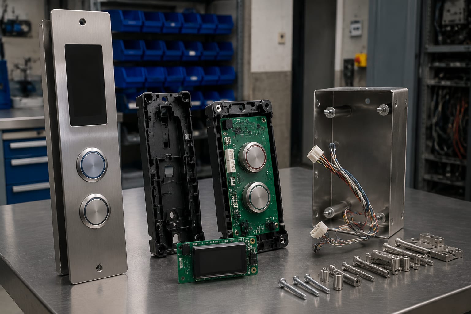
Never enlarge a panel cut-out, bend mounting clips or remove locating features simply to make an uncertain replacement fit. Such modifications can damage the panel, interfere with adjacent buttons or make later maintenance more difficult.
Where an assembly does not fit as expected, pause and recheck the part number, board revision and measurements. The mismatch may reveal that the item belongs to a different panel variant.
Check illumination and symbols
Illumination and symbols are both operational and usability requirements. The replacement must present the correct instruction to passengers and provide the expected visual feedback when the button is activated.
Confirm whether the existing Schindler button has:
- No illumination.
- A permanently lit legend.
- A ring or halo light.
- A symbol that changes state after a call is registered.
- An integrated display or directional indicator.
- A specific light colour or contrast arrangement.
- Braille, tactile markings or raised numerals.
- A floor number, letter, star marking, arrow or function pictogram.
Match the function before matching the colour. A down-arrow landing button is not interchangeable with an up-arrow button just because its dimensions and connector appear the same. Likewise, a door-open symbol must be matched to its intended function and panel position.
Check the site’s existing panel conventions carefully. Buildings may use G, 0, LG, B1, P1 or another notation for the same level type. The replacement should preserve the lift’s established floor identification rather than introduce a new, inconsistent label.
Illumination faults can also originate outside the button. Before replacing a complete assembly solely because it is dark, check whether the relevant supply, shared board or wiring circuit is functioning. A new illuminated button will not correct a panel-wide power or communication fault.
Verify board codes and connectors
Board code verification is one of the strongest safeguards when selecting Schindler button assemblies. Record every legible marking from the PCB, rear label and attached harness. Small differences in suffixes, revisions or connector layouts can indicate a different electrical design.
The minimum record should include:
- Full board code, including prefixes, suffixes and punctuation.
- Revision identifier.
- Number of connectors.
- Connector type, shape and keying.
- Pin count for each connector.
- Connector location and cable exit direction.
- Wire colours or harness labels, where present.
- Position of switches, LEDs, displays and mounting points.
- Clear front and rear photographs with a scale reference.
Do not rely only on wire colours. Wiring colours can vary between harnesses and are not a substitute for a connector or board-code match. Similarly, a plug that physically mates with a socket does not prove that the signal allocation is compatible.
Check connector condition before condemning the board
A loose plug, bent contact, damaged locking tab or oxidised connector can imitate a failed button board. Inspect both halves of the connection, including the cable side, before replacing the electronics.
Do not probe, bridge or alter lift-control wiring based on assumptions. Any electrical testing should be done with suitable equipment, documentation and competence for the specific lift system.
Test the panel after replacement
Testing should confirm more than whether the new button lights up. It must show that the panel function, indication and surrounding controls operate correctly without creating a new fault.
After the replacement is installed and the panel is reassembled, test in a controlled manner according to the site maintenance procedure:
- Confirm the button is securely mounted and flush with the panel.
- Check that the symbol, floor marking and orientation are correct.
- Verify normal illumination or display behaviour before activation, where applicable.
- Operate the button and confirm that it registers once and responds as intended.
- Check the corresponding call indication, direction indication or car command.
- Confirm adjacent buttons and display functions were not disturbed during the work.
- Inspect the panel for pinched cables, loose fixings or trapped components.
- Record the part fitted, board code and test result in the maintenance documentation.
For a COP floor button, testing normally includes confirming that the selected destination is accepted and that the call indication clears or changes at the appropriate time. For a LOP button, confirm that the correct direction is registered and that the lift responds according to normal group or single-lift operation.
A call response can be affected by traffic handling, collective control logic and other lift conditions. A delayed lift arrival does not automatically mean the new button is faulty. The key check is whether the panel registers the call correctly and the system behaves consistently with its normal operating logic.
Button sourcing checklist
Use this checklist when requesting or assessing Schindler buttons for replacement:
- [ ] Is it a COP, LOP, car command or special-function button?
- [ ] Which lift model family and panel type is it fitted to?
- [ ] Is the assembly mechanical push type or touch type?
- [ ] What is the complete board or part code?
- [ ] What revision number is marked on the PCB?
- [ ] What are the face, cut-out, depth and fixing measurements?
- [ ] How is it mounted: clips, screws, tabs or carrier?
- [ ] What connector type, pin count and keying does it use?
- [ ] Is the connector in the same rear position and orientation?
- [ ] What illumination method and indicator behaviour are required?
- [ ] Does the symbol, direction, floor legend and tactile marking match?
- [ ] Are there clear photographs of the front, rear, board code and installed position?
- [ ] Has the wider panel, harness or supply fault been ruled out?
- [ ] Will the replacement be installed and tested by competent lift personnel?
The most useful sourcing request combines the original board code with measurements, connector photographs and the panel position. This reduces the risk of selecting a similar-looking Schindler button that is unsuitable for the installation.
Common replacement mistakes
The most frequent error is ordering by front appearance alone. Lift buttons are small components, but their electronics, mounting and symbols are often application-specific.
Other avoidable mistakes include:
- Ordering an up or down hall-call button without confirming the required direction.
- Treating a board revision as unimportant.
- Measuring only the faceplate and not the cut-out or rear depth.
- Reusing a damaged or loose connector without inspection.
- Replacing several buttons when the actual fault is a shared board or power issue.
- Fitting a non-matching floor legend or inaccessible symbol arrangement.
- Testing only the replaced button and overlooking adjacent panel functions.
- Discarding the old part before all identifying markings and dimensions have been recorded.
FAQ
Can any button with the same size replace a Schindler button?
No. Physical size is only one check. The button must also match its function, mounting arrangement, illumination, board code, connector and panel application.
Is a 3300 button always compatible with a 3600 lift?
Not necessarily. Some related parts may be used across applications, but compatibility must be confirmed from the specific board code, connector layout, dimensions and panel configuration.
Should a dark button always be replaced?
Not immediately. A failed LED, local button fault, shared supply issue, wiring problem or panel-board fault can all cause missing illumination. Diagnose the fault before ordering an assembly.
What information is most important for a sourcing enquiry?
The complete PCB or part code, front and rear photos, connector details, measurements, button function and whether it is fitted in the COP or LOP provide the strongest basis for checking a match.
Kelevator supplies multi-brand lift spare parts for B2B importers, distributors, maintenance contractors, modernisation companies and OEM buyers. For a practical selection decision, compile the checklist details first and compare the proposed replacement against the removed Schindler button before installation.