
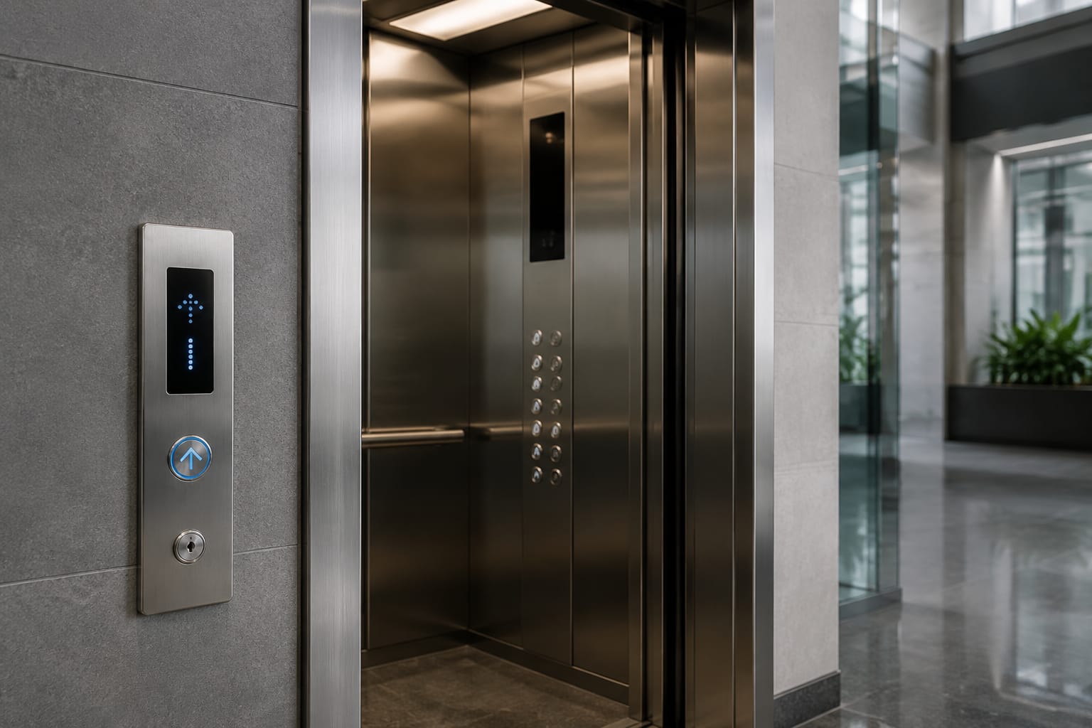
ThyssenKrupp elevator buttons should be sourced by their exact panel, board and physical details, not by the button’s appearance alone. A round or square pushbutton may look interchangeable, yet differ in mounting depth, cutout size, voltage, illumination, connector type or controller communication.
For a dependable replacement assessment, document where the component is fitted, photograph both sides, measure it carefully and capture every readable part number on the button, panel, display or circuit board. This approach is especially important when maintaining older equipment, mixed portfolios or modernised lifts where original components may no longer be available.
Car and landing button locations
Start by establishing whether the failed item is in the car operating panel (COP), at a landing entrance, or part of a separate indicator or call-board assembly. Its location narrows the likely component type and prevents a car button being specified as a hall-call button.
Inside the car, common locations include:
- The main COP, containing floor selection, door open, door close, alarm and other car controls
- An auxiliary panel, often used for a second entrance, service operation or rear door controls
- A key-switch or fire-service panel
- A car-position indicator or display section above or within the COP
- A destination-control interface in buildings using destination dispatch
At the landing, identify whether the part belongs to:
- A conventional up/down hall-call station
- A single-direction call point at a terminal floor
- A surface-mounted or flush-mounted landing panel
- An integrated display-and-call unit
- A destination-control terminal
Record the floor, entrance and travel direction. For example, “ground-floor main entrance, up/down landing station” is much more useful than “lift button required”. In a two-car or six-car group, also note whether the panel serves one lift or a shared landing system.
A replacement for a car operating panel can involve more than a single button. Where the fascia, button modules and display form an integrated assembly, a [customisable car operating panel, car button and display solution](/products/elevator-car-control-panel-car-button-display-cop-customization/) may be more relevant than sourcing a loose switch.
Identify the panel and controller family
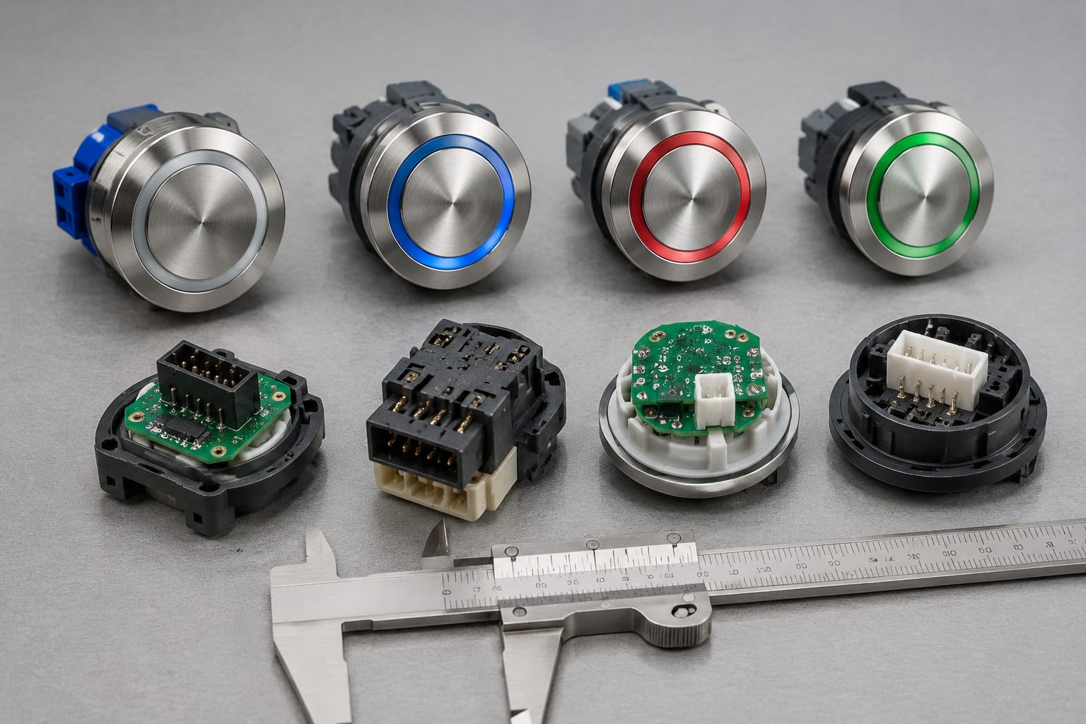
The manufacturer name on a lift does not identify every component fitted to it. A lift may have had a COP refurbishment, a replacement hall station or a controller upgrade during its service life. Treat the installed component as the item to identify.
First photograph the full panel straight on, including its surroundings. Then capture close views of the button face, the rear of the button module, labels, the PCB and all plugs. Use adequate lighting and retain original image files so small markings can be enlarged.
Useful identifiers include:
| Item to record | Why it matters |
|---|---|
| Lift or controller serial information | Helps link the component to the installed system where records are available |
| Panel reference, label or drawing number | Can identify the assembly rather than an individual button |
| Button module part number | The strongest starting point for an exact or compatible replacement |
| PCB code and revision | Distinguishes visually similar boards with different electronics |
| Board manufacturer markings | May identify an original equipment supplier or later replacement |
| Panel layout | Confirms the required number, positions and functions of controls |
| Floor naming scheme | Prevents errors between, for example, G, LG, P1, B1 and numbered levels |
| Installation or refurbishment date, if known | Gives useful context, but does not prove compatibility |
Do not rely only on generic descriptions such as “ThyssenKrupp round button” or “blue-lit lift button”. Multiple product families can use similar finishes and LED colours. A supplier should assess the evidence against the actual component, its operating environment and the interface it must join.
If no part number is visible, identify the assembly by a combination of panel photographs, dimensions, wiring, button function and board markings. This is slower than using an original reference, but usually provides a much stronger basis for comparison than a front photograph alone.
Separate original identity from replacement strategy
There are two distinct questions:
- What is currently installed?
- What replacement route is acceptable?
An exact replacement aims to retain the existing mounting, illumination, legends and electronics. A compatible replacement may require an adaptor, revised wiring, a matching set of buttons, or a new panel faceplate. A modernisation replacement can replace the complete call station or COP interface.
State which outcome is acceptable before seeking quotations. It avoids receiving an exact part when a panel renewal is needed, or being offered a generic button where electronic compatibility is essential.
Measure button and cutout dimensions
Measurements establish whether a candidate component can fit the existing panel and leave adequate clearance behind it. Measure the removed item where it is safe and practical to do so; a front-face measurement on an installed button is not enough.
Use a vernier calliper where possible and record dimensions in millimetres. Photograph the measurement with the calliper visible, particularly where an old part has no readable marking.
For each button or module, document:
- Visible face diameter, width and height
- Panel cutout diameter or aperture width and height
- Bezel outside dimensions
- Button body depth behind the panel
- Panel thickness
- Retaining clip, nut, screw or bracket arrangement
- Spacing to neighbouring buttons, displays and panel edges
- Position and size of any anti-rotation tab, locating peg or keyway
- Overall dimensions of a multi-button call-board or display module
A nominal “35 mm button”, for example, may refer to the visible ring, the mounting hole or the body diameter. Specify what was measured. For square buttons, provide both axes because a rectangular aperture cannot be inferred from a single dimension.
Check rear clearance before accepting a fit
A button that matches the face and cutout can still foul a back box, door jamb, cable loom or board behind the panel. This risk is common on slim landing stations and compact COPs.
Record available rear depth, the direction of cable exit and whether connectors point straight back or sideways. If the old component sits on a PCB, measure the board standoff and note whether the new part would contact other parts. Never force a component into a panel simply because the front bezel covers the opening.
Check illumination and tactile features
Illumination, legends and tactile features affect usability as well as appearance. Confirm the existing specification before choosing a replacement, particularly if only one button in a panel is being changed.
Document the following:
- Whether the button is unlit, permanently illuminated, or lights only after registration
- The colour of idle and registered indications
- The type of light source, where identifiable, such as LED
- Whether the illumination is a ring, halo, symbol, numeral or full face
- The floor label, pictogram and arrow orientation
- Whether the face is flush, concave, convex or raised
- Braille, raised numeral or tactile symbol details
- Audible feedback, if present
- Any contrasting ring, edge or face treatment
Photograph a lit button in both normal and registered states if the lift can be operated safely. A photo taken in bright daylight may conceal the light pattern, so a close image in lower ambient light can be useful.
Do not assume that a matching colour means an electrically matching light circuit. LED polarity, operating voltage, common supply arrangement and control method can vary. Similarly, a replacement with the same engraved floor number may have a different tactile profile or legend orientation.
When a whole landing call station needs renewal, compare products designed as a complete assembly rather than mixing separate faceplates, buttons and boards. A [touch hall-call button board for elevator applications](/products/touch-hall-call-touch-button-board-elevator-parts/) is relevant only where its interface, fitment and operational requirements are confirmed for the intended installation.
Record board codes and connectors
On electronic buttons, displays and hall-call stations, the circuit board often contains the most valuable identification information. Record every printed code, label and revision suffix exactly, including punctuation. A single character can distinguish revisions that are not interchangeable.
Capture:
- PCB part number and revision
- Sticker labels, barcodes and serial markings
- Connector reference designators, such as J1 or CN2
- Number of connectors and pins
- Plug housing shape, keying and latch position
- Wire colours and terminal labels
- Dip-switch positions, jumpers or address links
- Visible signs of repair, corrosion, heat damage or altered wiring
Take one photograph that shows the whole board in context, then separate close-ups of each connector and code. For plug faces, photograph the pin side without disconnecting wiring unnecessarily. If a plug must be removed during authorised maintenance, label it first and ensure the lift is isolated according to the applicable site procedures.
Connector matching is not enough
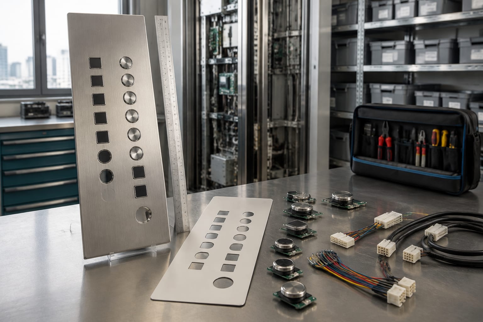
Two boards can have the same connector housing and pin count yet carry different signals or addressing. Conversely, boards in one system may use different connectors despite performing related functions. A candidate board must be checked for electrical and communication compatibility, not merely physical connection.
Avoid transferring a board from another lift as a trial unless its configuration is understood. It can introduce incorrect floor addressing, failed call registration, display faults or damage. A controlled compatibility review should consider the installed controller, wiring, software configuration and system topology.
Evaluate display and call-board integration
A display or hall-call board may be a standalone component, but it can also be part of a networked system. Before replacing it, determine what functions are combined in the assembly.
Typical combinations include:
- Up and down call buttons with arrow indicators
- A floor-position display with direction arrows
- A destination keypad or touch interface
- Separate button modules connected to one common board
- A display board receiving commands from a remote call-board
- A networked landing device with an address set by switches, jumpers or software
For each assembly, identify the cable count and routing. A two-wire connection might indicate a bus-type arrangement, but wire count alone does not establish the protocol. Avoid describing a component as “standard” unless the controller documentation or a qualified assessment confirms it.
Where a known call display board reference is available, compare the full reference, revision and connector arrangement against [3600/5200 elevator call display board and button parts](/products/3600-5200-elevator-call-display-board-button-lift-parts-accessories/). Confirm suitability against the installed system before purchase; a matching family name or similar product image is insufficient.
When replacement of one part is impractical
A single failed button is often serviceable, but replacement of one component may be unsuitable when:
- The original button is discontinued and no verified equivalent is available
- The new illumination differs visibly from the remaining buttons
- The board has corrosion or repeated intermittent faults
- The call station has obsolete electronics that cannot be supported independently
- The panel face is damaged or apertures do not suit available replacements
- A controller upgrade has changed the required interface
In these cases, replacement of a complete call station, display-and-button assembly or COP section may offer a more coherent outcome. The correct choice depends on the condition of the installation, required appearance, available documentation and the scope of the modernisation.
Accessibility and durability checks
A suitable elevator button must work reliably in its actual environment and support usable, legible controls. Do not reduce the decision to fitment and electrical operation.
For accessibility, check that the proposed arrangement preserves or improves:
- Clear, unambiguous floor identification
- Tactile and Braille features where present or required for the project
- Sufficient visual contrast between control, legend and surrounding panel
- Readable illumination in the site’s lighting conditions
- Logical placement of door controls, alarm controls and landing directions
- Consistency across a group of lifts where users expect the same layout
For durability, consider the installation context. A busy residential building, retail centre, healthcare site, industrial facility and coastal property can place different demands on buttons and faceplates. Confirm the expected use, exposure to cleaning products, risk of vandalism, moisture ingress, dust, temperature conditions and frequency of use.
Stainless steel, plastic and glass-faced components can each be appropriate in different contexts, but their suitability depends on the complete assembly and its stated specification. Do not infer impact resistance, ingress protection, fire performance or accessibility compliance from a finish or a product photograph. Confirm relevant project requirements and documentation with the responsible lift professional.
Prepare a complete sourcing request
A good sourcing request gives a supplier enough information to determine whether an exact part, compatible alternative or assembly replacement is possible. It also reduces follow-up questions and the risk of ordering an unusable item.
Include this checklist:
- Component required and quantity
- Car or landing location, floor and entrance
- Full lift, controller and panel identification available on site
- Clear front, rear, side and installed-context photographs
- All part numbers, PCB codes, revisions and labels
- Dimensions of the button, bezel, cutout, panel thickness and rear clearance
- Button function and floor legend
- Illumination behaviour and colour
- Tactile, Braille and audible-feedback requirements
- Connector photographs, pin count, wiring details and addressing information
- Whether the request is for an exact replacement, compatible part, repair assessment or full assembly
- Any requirement to match existing panel finishes or group-wide layout
- Condition of the existing part and reason for replacement
Use precise wording where uncertainty exists. For example: “Part number unreadable; photos attached; 38 mm circular cutout measured; blue ring illuminates on call registration; five-pin keyed plug.” This is more useful than claiming a component number that has not been verified.
Kelevator supplies multi-brand elevator spare parts for B2B importers, distributors, maintenance contractors and OEM buyers. For a practical compatibility assessment, provide the complete record above and ask the supplier to identify which details are confirmed, which require verification and whether a component, board or complete panel replacement is the appropriate route.
Common sourcing mistakes to avoid
The most common mistake is ordering from a front photograph alone. Similar-looking buttons can differ behind the panel, and the cost of return, downtime and repeat attendance can exceed the saving from a quick selection.
Other avoidable errors include:
- Using the lift brand as the only identifier
- Measuring only the visible button face, not the cutout and rear depth
- Omitting the PCB revision or connector photographs
- Replacing one illuminated button without checking colour and brightness matching
- Ignoring panel thickness and fixing method
- Assuming a plug-fit board shares the same electrical or communication function
- Failing to record landing direction, floor naming and entrance location
- Treating a worn panel as a single-button fault when broader renewal is needed
FAQ
Can a generic elevator button replace a ThyssenKrupp button?
Sometimes, but only after physical, electrical and functional compatibility has been checked. A generic pushbutton may fit the panel yet have unsuitable illumination, mounting, connector or control characteristics. It is generally more appropriate for a planned panel adaptation than as an assumed direct replacement.
Is the controller serial number enough to identify the correct part?
No. It is useful context, but the panel, button module and board may have been changed independently. Include the controller information alongside component markings, photographs, measurements and connector details.
Should a complete panel be replaced when one button fails?
Not necessarily. A single button replacement may be appropriate when the component is identifiable and the panel is otherwise sound. Consider a larger replacement where the part is obsolete, multiple items are degraded, the electronics are unreliable or a consistent new appearance is required.
What photographs should be included in a sourcing enquiry?
Include the full car or landing panel, a close front view of the failed component, its rear and side profile, the cutout if accessible, all labels and PCB codes, every connector and the assembly installed in context. Add photographs of illumination and tactile markings where relevant.
A complete identification record is the best starting point for sourcing ThyssenKrupp elevator buttons. Confirm the physical fit, electrical interface, panel integration and user-facing features before placing an order, then retain the resulting part references and photographs in the lift’s maintenance records.